
Page 257 - Fundamentals of Gas Shale Reservoirs
P. 257
INTEGRATING, INTERPRETING, AND USING PASSIVE SEISMIC DATA 237
results of this method are identical to the standard averaging orientations (e.g., Frohlich, 1994; Tibi et al., 1999). Based
method for DC moment tensors, but provide additional on this notion, the complexity arising from changes in frac
information. The extra information is the fraction of the bulk ture orientations for an MEQ‐generating fracture network
strain that is simple shear and the fraction that is shape can be assessed by evaluating the percentage of CLVD com
distortion without volume change. The simple shear fraction ponent in the composite moment tensor of the DC events
(like shearing a deck of cards) is termed the DC component induced in the reservoir.
(for double‐couple). The shape distortion component is Case Study 1. Figure 10.27 shows the locations along
termed the CLVD component (for compensated linear vector with the inferred fault plane solutions for 38 MEQs induced
dipole). This method is summarized in the following during a hydraulic fracture treatment. The DC focal mecha
paragraphs, and applied to two case studies. Another way to nisms were determined using Snoke’s (2003) code, by
think about the DC and CLVD components is as measures of searching for the fault plane solutions that best fit the first
complexity of movement planes and directions within the motion polarities of P‐waves (Tibi et al., 2013). The MEQs
reservoir, and hence as a measure of fracture complexity show three focal mechanism types. Most of the events
induced by the fracture treatment.
The seismic consistency concept was introduced by
Frohlich and Apperson (1992) as a measure of similarity of
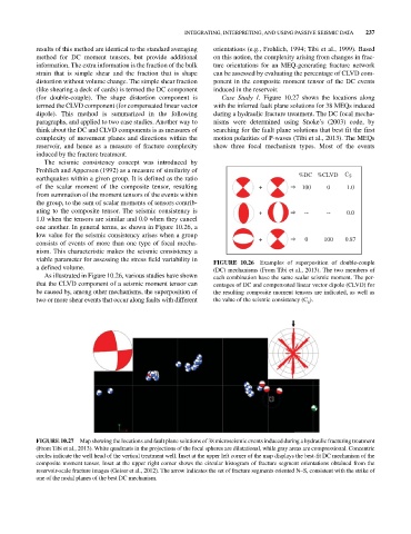
earthquakes within a given group. It is defined as the ratio %DC %CLVD C S
of the scalar moment of the composite tensor, resulting + 100 0 1.0
from summation of the moment tensors of the events within
the group, to the sum of scalar moments of tensors contrib
uting to the composite tensor. The seismic consistency is + -- -- 0.0
1.0 when the tensors are similar and 0.0 when they cancel
one another. In general terms, as shown in Figure 10.26, a
low value for the seismic consistency arises when a group
consists of events of more than one type of focal mecha + 0 100 0.87
nism. This characteristic makes the seismic consistency a
viable parameter for assessing the stress field variability in FIGURE 10.26 Examples of superposition of double‐couple
a defined volume. (DC) mechanisms (From Tibi et al., 2013). The two members of
As illustrated in Figure 10.26, various studies have shown each combination have the same scalar seismic moment. The per
that the CLVD component of a seismic moment tensor can centages of DC and compensated linear vector dipole (CLVD) for
be caused by, among other mechanisms, the superposition of the resulting composite moment tensors are indicated, as well as
two or more shear events that occur along faults with different the value of the seismic consistency (C ).
S
FIGURE 10.27 Map showing the locations and fault plane solutions of 38 microseismic events induced during a hydraulic fracturing treatment
(From Tibi et al., 2013). White quadrants in the projections of the focal spheres are dilatational, while gray areas are compressional. Concentric
circles indicate the well head of the vertical treatment well. Inset at the upper left corner of the map displays the bestfit DC mechanism of the
composite moment tensor. Inset at the upper right corner shows the circular histogram of fracture segment orientations obtained from the
reservoir‐scale fracture images (Geiser et al., 2012). The arrow indicates the set of fracture segments oriented N–S, consistent with the strike of
one of the nodal planes of the best DC mechanism.