
Page 189 - Fundamentals of Light Microscopy and Electronic Imaging
P. 189
172 DIC MICROSCOPY AND MODULATION CONTRAST MICROSCOPY
features of the specimen at different azimuths, it is necessary to rotate the specimen on
the microscope stage.
Gordon Ellis demonstrated that the mechanism of contrast generation in this and
other schlieren-related systems is based on the selective removal of diffracted light on
th
one side of the 0 -order spot in the diffraction plane. This demonstration was made on
a schlieren microscope of his own design: the single sideband edge-enhancement
(SSEE) microscope. As in the Hoffman MCM microscope, there are complementary
masks (half-aperture masks) in the front aperture of the condenser and in the back aper-
ture of the objective. Ellis demonstrated (1978) that a transparent object (a water-
immersed diffraction grating replica), which is invisible without the masks in a focused
bright-field image, becomes visible at focus when the diffracted light of one sideband is
blocked by the objective aperture mask. In the demonstration, there was no modification
of the direct light, so it is possible to conclude that formation of a visible image is
strictly a consequence of the change in interference between the diffracted sidebands
and the direct light.
Alignment of the Modulation Contrast Microscope
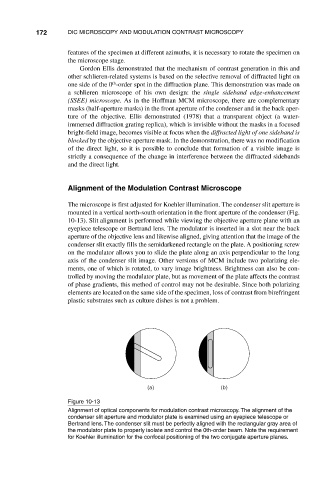
The microscope is first adjusted for Koehler illumination. The condenser slit aperture is
mounted in a vertical north-south orientation in the front aperture of the condenser (Fig.
10-13). Slit alignment is performed while viewing the objective aperture plane with an
eyepiece telescope or Bertrand lens. The modulator is inserted in a slot near the back
aperture of the objective lens and likewise aligned, giving attention that the image of the
condenser slit exactly fills the semidarkened rectangle on the plate. A positioning screw
on the modulator allows you to slide the plate along an axis perpendicular to the long
axis of the condenser slit image. Other versions of MCM include two polarizing ele-
ments, one of which is rotated, to vary image brightness. Brightness can also be con-
trolled by moving the modulator plate, but as movement of the plate affects the contrast
of phase gradients, this method of control may not be desirable. Since both polarizing
elements are located on the same side of the specimen, loss of contrast from birefringent
plastic substrates such as culture dishes is not a problem.
(a) (b)
Figure 10-13
Alignment of optical components for modulation contrast microscopy. The alignment of the
condenser slit aperture and modulator plate is examined using an eyepiece telescope or
Bertrand lens. The condenser slit must be perfectly aligned with the rectangular gray area of
the modulator plate to properly isolate and control the 0th-order beam. Note the requirement
for Koehler illumination for the confocal positioning of the two conjugate aperture planes.