
Page 229 - Fundamentals of Light Microscopy and Electronic Imaging
P. 229
212 CONFOCAL LASER SCANNING MICROSCOPY
3 mW HeNe laser
10 mm
50 mm focal length lens
30 mm
2 mm
15 mm 30 mm
40x Coverslip
Coin objective TV camera
Rigid White card and monitor
support with pinhole (optional)
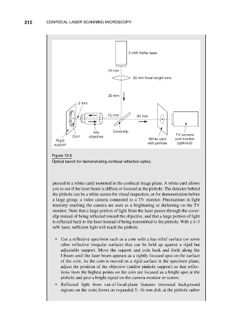
Figure 12-6
Optical bench for demonstrating confocal reflection optics.
pierced in a white card) mounted in the confocal image plane. A white card allows
you to see if the laser beam is diffuse or focused at the pinhole. The detector behind
the pinhole can be a white screen for visual inspection, or for demonstration before
a large group, a video camera connected to a TV monitor. Fluctuations in light
intensity reaching the camera are seen as a brightening or darkening on the TV
monitor. Note that a large portion of light from the laser passes through the cover-
slip instead of being reflected toward the objective, and that a large portion of light
is reflected back to the laser instead of being transmitted to the pinhole. With a 1–3
mW laser, sufficient light will reach the pinhole.
• Use a reflective specimen such as a coin with a bas relief surface (or some
other reflective irregular surface) that can be held up against a rigid but
adjustable support. Move the support and coin back and forth along the
I-beam until the laser beam appears as a tightly focused spot on the surface
of the coin. As the coin is moved on a rigid surface in the specimen plane,
adjust the position of the objective (and/or pinhole support) so that reflec-
tions from the highest points on the coin are focused as a bright spot at the
pinhole and give a bright signal on the camera monitor or screen.
• Reflected light from out-of-focal-plane features (recessed background
regions on the coin) forms an expanded 5–10 mm disk at the pinhole rather