
Page 228 - Fundamentals of Light Microscopy and Electronic Imaging
P. 228
THE OPTICAL PRINCIPLE OF CONFOCAL IMAGING 211
Galvanometer
mirror
Laser beam
Specimen
Scanning
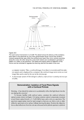
Figure 12-5
The scan-control mechanism in a CLSM. The sketch shows the delivery of the excitatory
laser beam to the specimen by one of two galvanometer-driven mirrors that vibrate in
mutually perpendicular axes within the confocal scan head. One mirror controls scanning
along the x-axis, the other along the y-axis; both motions are coordinated to generate a
pattern of a raster on the specimen. The speed and angular extent of deflection of the
mirrors can be controlled to regulate the scanning rate and the extent of the scan.
a computer monitor. Thus, a confocal image of an object is reconstructed from pho-
ton signals and is displayed by a computer; the confocal image never exists as a real
image that can be seen by the eye in the microscope.
• A microscope system of this design is called a confocal laser scanning microscope
(CLSM).
Demonstration: Isolation of Focal Plane Signals
with a Confocal Pinhole
Warning—Care should be taken not to accidentally reflect the light beam into the
eye during this exercise!
To become familiar with confocal optics, construct the confocal reflection
optical system shown in Figure 12-6 using common optical components mounted
on an I-beam optical bench, a 1–5 mW HeNe laser, and a coin as a specimen. The
specimen support plate must be rigid enough so that you can slide a coin or other
reflective specimen on its surface without moving the plate. Position the objective
lens so that reflections from the coin are refocused at the pinhole aperture (a pinhole