
Page 226 - Fundamentals of Light Microscopy and Electronic Imaging
P. 226
THE OPTICAL PRINCIPLE OF CONFOCAL IMAGING 209
PMT
Pinhole
EM
Barrier filter
EX
Dichroic
mirror Laser
Scan control
Objective lens
Specimen
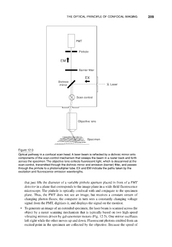
Figure 12-3
Optical pathway in a confocal scan head. A laser beam is reflected by a dichroic mirror onto
components of the scan-control mechanism that sweeps the beam in a raster back and forth
across the specimen. The objective lens collects fluorescent light, which is descanned at the
scan control, transmitted through the dichroic mirror and emission (barrier) filter, and passes
through the pinhole to a photomultiplier tube. EX and EM indicate the paths taken by the
excitation and fluorescence emission wavelengths.
that just fills the diameter of a variable pinhole aperture placed in front of a PMT
detector in a plane that corresponds to the image plane in a wide-field fluorescence
microscope. The pinhole is optically confocal with and conjugate to the specimen
plane. Thus, the PMT does not see an image, but receives a constant stream of
changing photon fluxes; the computer in turn sees a constantly changing voltage
signal from the PMT, digitizes it, and displays the signal on the monitor.
• To generate an image of an extended specimen, the laser beam is scanned across the
object by a raster scanning mechanism that is typically based on two high-speed
vibrating mirrors driven by galvanometer motors (Fig. 12-5). One mirror oscillates
left-right while the other moves up and down. Fluorescent photons emitted from an
excited point in the specimen are collected by the objective. Because the speed of