
Page 48 - Fundamentals of Radar Signal Processing
P. 48
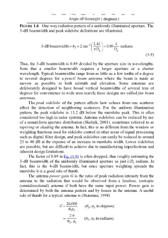
FIGURE 1.6   One-way radiation pattern of a uniformly illuminated aperture. The
               3-dB beamwidth and peak sidelobe definitions are illustrated.


                                                                                                        (1.9)

               Thus, the 3-dB beamwidth is 0.89 divided by the aperture size in wavelengths.
               Note  that  a  smaller  beamwidth  requires  a  larger  aperture  or  a  shorter
               wavelength. Typical beamwidths range from as little as a few tenths of a degree
               to  several  degrees  for  a pencil  beam  antenna  where  the  beam  is  made  as
               narrow  as  possible  in  both  azimuth  and  elevation.  Some  antennas  are
               deliberately  designed  to  have  broad  vertical  beamwidths  of  several  tens  of
               degrees for convenience in wide area search; these designs are called fan beam
               antennas.

                     The peak sidelobe  of  the  pattern  affects  how  echoes  from  one  scatterer
               affect  the  detection  of  neighboring  scatterers.  For  the  uniform  illumination
               pattern, the peak sidelobe is 13.2 dB below the mainlobe peak. This is often
               considered too high in radar systems. Antenna sidelobes can be reduced by use
               of a nonuniform aperture distribution (Skolnik, 2001), sometimes referred to as

               tapering or shading the antenna. In fact, this is no different from the window or
               weighting functions used for sidelobe control in other areas of signal processing
               such as digital filter design, and peak sidelobes can easily be reduced to around
               25 to 40 dB at the expense of an increase in mainlobe width. Lower sidelobes
               are possible, but are difficult to achieve due to manufacturing imperfections and
               inherent design limitations.
                     The factor of 0.89 in Eq. (1.9) is often dropped, thus roughly estimating the

               3-dB beamwidth of the uniformly illuminated aperture as just λ/D  radians. In
                                                                                               y
               fact,  this  is  the  4-dB  beamwidth,  but  since  aperture  weighting  spreads  the
               mainlobe it is a good rule of thumb.
                     The antenna power gain G is the ratio of peak radiation intensity from the
               antenna  to  the  radiation  that  would  be  observed  from  a  lossless,  isotropic
               (omnidirectional)  antenna  if  both  have  the  same  input  power.  Power  gain  is

               determined by both the antenna pattern and by losses in the antenna. A useful
               rule of thumb for a typical antenna is (Stutzman, 1998)