
Page 53 - Fundamentals of Radar Signal Processing
P. 53
array from off broadside.
The discussion so far has been phrased in terms of the transmit antenna
pattern (for aperture antennas) or the receive pattern (for arrays), but not both.
The patterns described have been one-way antenna patterns. The reciprocity
theorem guarantees that the receive antenna pattern is identical to the transmit
antenna pattern (Balanis, 2005). Consequently, for a monostatic radar, the two-
way antenna pattern (power or voltage) is just the square of the corresponding
one-way pattern. It also follows that the antenna phase center is the same in both
transmit and receive modes.
1.3.3 Receivers
It was shown in Sec. 1.3.1 that radar signals are usually narrowband, bandpass,
phase- or frequency-modulated functions. This means that the echo waveform
r(t) received from a single scatterer is of the form
(1.17)
where the amplitude modulation A(t) represents only the pulse envelope. The
major function of the receiver processing is demodulation of the information
bearing part of the radar signal to baseband, with the goal of measuring θ(t).
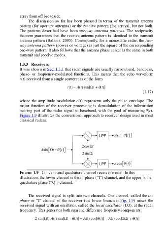
Figure 1.9 illustrates the conventional approach to receiver design used in most
classical radars.
FIGURE 1.9 Conventional quadrature channel receiver model. In this
illustration, the lower channel is the in-phase (“I”) channel, and the upper is the
quadrature phase (“Q”) channel.
The received signal is split into two channels. One channel, called the in-
phase or “I” channel of the receiver (the lower branch in Fig. 1.9) mixes the
received signal with an oscillator, called the local oscillator (LO), at the radar
frequency. This generates both sum and difference frequency components: