
Page 57 - Fundamentals of Radar Signal Processing
P. 57
and Q channels must be exactly in quadrature, that is, 90° out of phase with one
another.
In the receiver structure shown in Fig. 1.9, the information-bearing portion
of the signal is demodulated from the carrier frequency to baseband in a single
mixing operation. While convenient for analysis, pulsed radar receivers are
virtually never implemented this way in practice. One reason is that active
electronic devices introduce various types of noise into their output signal, such
as shot noise and thermal noise. One noise component, known as flicker noise
–1
or 1/F noise, has a power spectrum that behaves approximately as F and is
therefore strongest near zero frequency. Since received radar signals are very
weak, they can be corrupted by 1/F noise if they are translated to baseband
before being amplified.
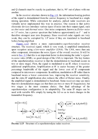
Figure 1.13 shows a more representative superheterodyne receiver
structure. The received signal, which is very weak, is amplified immediately
upon reception using a low-noise amplifier (LNA). The LNA, more than any
other component, determines the noise figure of the overall receiver. It will be
seen in Sec. 2.3 that this is an important factor in determining the radar’s signal-
to-noise ratio (SNR), so good design of the LNA is important. The key feature
of the superheterodyne receiver is that the demodulation to baseband occurs in
two or more stages. First, the signal is modulated to an IF, where it receives
additional amplification. Amplification at IF is easier because of the greater
percentage bandwidth of the signal and the lower cost of IF components
compared to microwave components. In addition, modulation to IF rather than to
baseband incurs a lower conversion loss, improving the receiver sensitivity,
and the extra IF amplification also reduces the effect of flicker noise. Finally,
the amplified signal is demodulated to baseband. Some receivers may use more
than two demodulation stages (so that there are two or more IF frequencies), but
two stages is the most common choice. One final advantage of the
superheterodyne configuration is its adaptability. The same IF stages can be
used with variable RFs simply by tuning the LO so as to track changes in the
transmitted frequency.
FIGURE 1.13 Structure of a superheterodyne radar receiver.