
Page 52 - Fundamentals of Radar Signal Processing
P. 52
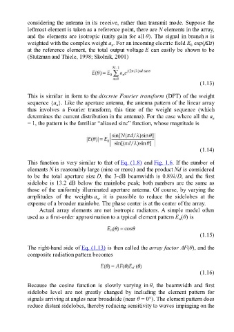
considering the antenna in its receive, rather than transmit mode. Suppose the

               leftmost element is taken as a reference point, there are N elements in the array,
               and the elements are isotropic (unity gain for all θ). The signal in branch n is
               weighted with the complex weight a . For an incoming electric field E  exp(jΩt)
                                                                                                  0
                                                          n
               at the reference element, the total output voltage E can easily be shown to be
               (Stutzman and Thiele, 1998; Skolnik, 2001)


                                                                                                       (1.13)

               This is similar in form to the discrete Fourier transform (DFT) of the weight
               sequence {a }. Like the aperture antenna, the antenna pattern of the linear array
                              n
               thus  involves  a  Fourier  transform,  this  time  of  the  weight  sequence  (which
               determines the current distribution in the antenna). For the case where all the a             n
               = 1, the pattern is the familiar “aliased sinc” function, whose magnitude is


                                                                                                       (1.14)

               This function is very similar to that of Eq. (1.8) and Fig. 1.6. If the number of
               elements N is reasonably large (nine or more) and the product Nd is considered
               to  be  the  total  aperture  size D, the 3-dB beamwidth is 0.89λ/D, and the first
               sidelobe is 13.2 dB below the mainlobe peak; both numbers are the same as
               those of the uniformly illuminated aperture antenna. Of course, by varying the

               amplitudes  of  the  weights a ,  it  is  possible  to  reduce  the  sidelobes  at  the
                                                  n
               expense of a broader mainlobe. The phase center is at the center of the array.
                     Actual  array  elements  are  not  isotropic  radiators. A  simple  model  often
               used as a first-order approximation to a typical element pattern E (θ) is
                                                                                            el


                                                                                                       (1.15)

               The right-hand side of Eq. (1.13) is then called the array factor AF(θ), and the
               composite radiation pattern becomes


                                                                                                       (1.16)

               Because  the  cosine  function  is  slowly  varying  in θ,  the  beamwidth  and  first
               sidelobe  level  are  not  greatly  changed  by  including  the  element  pattern  for
               signals arriving at angles near broadside (near θ = 0°). The element pattern does
               reduce distant sidelobes, thereby reducing sensitivity to waves impinging on the