
Page 54 - Fundamentals of Radar Signal Processing
P. 54
(1.18)
The sum term is then removed by the lowpass filter, leaving only the modulation
term A(t)cos[θ(t)]. The other channel, called the quadrature phase or “Q”
channel, mixes the signal with an oscillator having the same frequency but a 90°
phase shift from the I channel oscillator. The Q channel mixer output is
(1.19)
which, after filtering, leaves the modulation term A(t)sin[θ(t)]. If the input r(t) is
written as A(t)cos[Ωt + θ(t)] instead, the upper channel of Fig. 1.9 becomes the
I channel and the lower the Q channel, with outputs A(t)cos[θ(t)] and
–A(t)sin[θ(t)], respectively. In general, the I channel is the one where the
oscillator function (sine or cosine) is the same as that used in modeling the
signal.
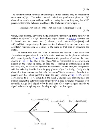
The reason that both the I and Q channels are needed is that either one
alone does not provide sufficient information to determine the phase modulation
θ(t) unambiguously. Figure 1.10 illustrates the problem. Consider the case
shown in Fig. 1.10a. The signal phase θ(t) is represented as a solid black
phasor in the complex plane. If only the I channel is implemented in the
receiver, only the cosine of θ(t) will be measured. In this case, the true phasor
will be indistinguishable from the gray phasor –θ(t). Similarly, if only the Q
channel is implemented so that only the sine of θ(t) is measured, then the true
phasor will be indistinguishable from the gray phasor of Fig. 1.10b, which
corresponds to π – θ(t). When both the I and Q channels are implemented, the
4
phasor quadrant is determined unambiguously. In fact, the signal processor will
normally assign the I signal to be the real part of a complex signal and the Q
signal to be the imaginary part, forming a single complex signal