
Page 55 - Fundamentals of Radar Signal Processing
P. 55
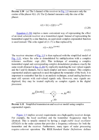
FIGURE 1.10   (a) The I channel of the receiver in Fig. 1.9 measures only the
               cosine of the phasor θ(t). (b) The Q channel measures only the sine of the
               phasor.


                                                                                                       (1.20)

                     Equation (1.20) implies a more convenient way of representing the effect
               of an ideal coherent receiver on a transmitted signal. Instead of representing the
               transmitted signal by a sine function, an equivalent complex exponential function

               is used instead.  The echo signal of (1.17) is thus replaced by
                                 5


                                                                                                       (1.21)

               The receiver structure of Fig. 1.9 is then replaced with the simplified model of
               Fig.  1.11,  where  the  echo  is  demodulated  by  multiplication  with  a  complex
               reference  oscillator  exp(– jΩt).  This  technique  of  assuming  a  complex
               transmitted signal and corresponding complex demodulator produces exactly the

               same result obtained in Eq. (1.20) by explicitly modeling the real-valued signals
               and the I and Q channels, but is much simpler and more compact. This complex
               exponential analysis approach is used throughout the remainder of the book. It is
               important to remember that this is an analysis technique; actual analog hardware
               must  still  operate  with  real-valued  signals  only.  However,  once  signals  are
               digitized,  they  may  be  treated  explicitly  as  complex  signals  in  the  digital
               processor.


               FIGURE 1.11   Simplified transmission and receiver model using complex
               exponential signals.


                     Figure 1.9 implies several requirements on a high-quality receiver design.
               For  example,  the  local  oscillator  and  the  transmitter  frequencies  must  be
               identical.  This  is  usually  ensured  by  having  a  single stable  local  oscillator
               (STALO) in the radar system that provides a frequency reference for both the
               transmitter  and  the  receiver.  Furthermore,  many  types  of  radar  processing
               require coherent  operation.  The  IEEE Standard  Radar  Definitions  defines