
Page 62 - Fundamentals of Radar Signal Processing
P. 62
This description of range resolution applies only to unmodulated, constant
frequency pulses. As will be seen in Chap. 4, pulse modulation combined with
matched filtering can be used to obtain range resolution finer than cτ/2.
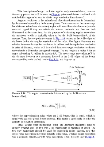
Angular resolution in the azimuth and elevation dimensions is determined
by the antenna beamwidths in the same planes. Two scatterers at the same range
but different azimuth (or elevation) angles will contribute simultaneously to the
received signal if they are within the antenna mainlobe and thus are both
illuminated at the same time. For the purpose of estimating angular resolution,
the mainlobe width is typically taken to be the 3-dB beamwidth θ of the
3
antenna. Thus, the two point scatterers in Fig. 1.16 located at the 3-dB edges of
the beam define the angular resolution of the radar. The figure illustrates the
relation between the angular resolution in radians and the equivalent resolution
in units of distance, which will be called the cross-range resolution to denote
resolution in a dimension orthogonal to range. The arc length at a radius R for an
angle subtending θ radians is exactly Rθ . The cross-range resolution ΔCR is
3
3
the distance between two scatterers located at the 3-dB edges of the beam,
corresponding to the dashed line in Fig. 1.16, and is given by
FIGURE 1.16 The angular resolution is determined by the 3-dB antenna
beamwidth θ .
3
(1.26)
where the approximation holds when the 3-dB beamwidth is small, which is
usually the case for pencil beam antennas. This result is applicable in either the
azimuth or elevation dimension.
Three details bear mentioning. First, the literature frequently fails to
specify whether one- or two-way 3-dB beamwidth is required or given. The
two-way beamwidth should be used for monostatic radar. Second, note that
cross-range resolution increases linearly with range, whereas range resolution
was a constant. Finally, as with range resolution, it will be seen later (Chap. 8)