
Page 132 - Fundamentals of The Finite Element Method for Heat and Fluid Flow
P. 132
STEADY STATE HEAT CONDUCTION IN ONE DIMENSION
124
Exercise 4.6.4 A circular fin of inner diameter 20 cm and outer diameter of 26 cm transfers
◦
heat from a small motorcycle engine. If the average engine surface temperature is 112 C,
determine the temperature distribution along the fin surface. The thermal conductivity of the
◦
fin material is 21 W/m C and the convective heat transfer coefficient between the fin and
the atmosphere is 120 W/m 2 ◦ C. Assume an atmospheric temperature of 32 C.
◦
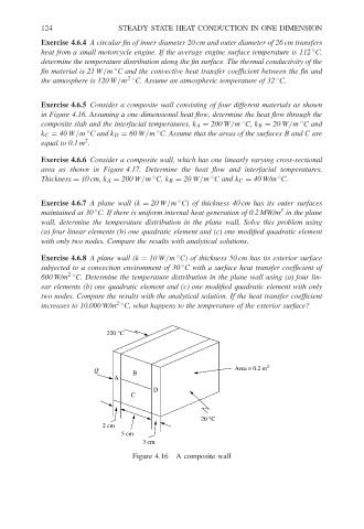
Exercise 4.6.5 Consider a composite wall consisting of four different materials as shown
in Figure 4.16. Assuming a one-dimensional heat flow, determine the heat flow through the
◦
composite slab and the interfacial temperatures. k A = 200 W/m C, k B = 20 W/m C and
◦
◦
◦
k C = 40 W/m C and k D = 60 W/m C. Assume that the areas of the surfaces B and C are
2
equal to 0.1 m .
Exercise 4.6.6 Consider a composite wall, which has one linearly varying cross-sectional
area as shown in Figure 4.17. Determine the heat flow and interfacial temperatures.
◦
◦
◦
Thickness = 10 cm, k A = 200 W/m C, k B = 20 W/m C and k C = 40 W/m C.
Exercise 4.6.7 A plane wall (k = 20 W/m C) of thickness 40 cm has its outer surfaces
◦
3
maintained at 30 C. If there is uniform internal heat generation of 0.2 MW/m in the plane
◦
wall, determine the temperature distribution in the plane wall. Solve this problem using
(a) four linear elements (b) one quadratic element and (c) one modified quadratic element
with only two nodes. Compare the results with analytical solutions.
◦
Exercise 4.6.8 A plane wall (k = 10 W/m C) of thickness 50 cm has its exterior surface
◦
subjected to a convection environment of 30 C with a surface heat transfer coefficient of
600 W/m 2 ◦ C. Determine the temperature distribution in the plane wall using (a) four lin-
ear elements (b) one quadratic element and (c) one modified quadratic element with only
two nodes. Compare the results with the analytical solution. If the heat transfer coefficient
increases to 10,000 W/m 2 ◦ C, what happens to the temperature of the exterior surface?
220 °C
Q Area = 0.2 m 2
B
A
D
C
20 °C
2 cm
5 cm
3 cm
Figure 4.16 A composite wall