
Page 125 - Fundamentals of Water Treatment Unit Processes : Physical, Chemical, and Biological
P. 125
80 Fundamentals of Water Treatment Unit Processes: Physical, Chemical, and Biological
TABLE 5.1
Bar Screen Openings
Opening
Type of Bar Screen (mm) (in.) Material Screened
Trash racks in rivers for 80–160 3–6 Logs, timbers, stumps
water treatment plant
intakes
Bar screen ahead 50–150 2–6 Large objects, rags
of raw sewage pumps
and grit chambers
Bar screen ahead of 20–50 0.75–2
other devices or
processes (a) (b)
Comminuting 6–20 0.25–0.75 Clinging materials
3
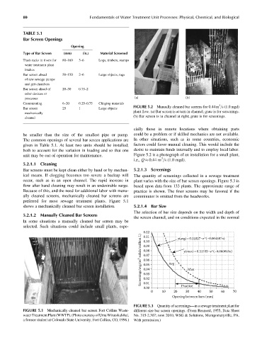
FIGURE 5.2 Manually cleaned bar screens for 0.44 m =s (1.0 mgd)
Bar screen 25 1 Large objects
plant flow. (a) Bar screen is at turn in channel; grate is for screenings.
mechanically
(b) Bar screen is in channel at right; grate is for screenings.
cleaned
cially those in remote locations where obtaining parts
be smaller than the size of the smallest pipe or pump. could be a problem or if skilled mechanics are not available.
The common openings of several bar screen applications are In other situations, such as in some countries, economic
given in Table 5.1. At least two units should be installed; factors could favor manual cleaning. This would include the
both to account for the variation in loading and so that one desire to maintain funds internally and to employ local labor.
unit may be out of operation for maintenance. Figure 5.2 is a photograph of an installation for a small plant,
3
i.e., Q 0.44 m =s (1.0 mgd).
5.2.1.1 Cleaning
Bar screens must be kept clean either by hand or by mechan- 5.2.1.3 Screenings
ical means. If clogging becomes too severe a backup will The quantity of screenings collected in a sewage treatment
occur, such as in an open channel. The rapid increase in plant varies with the size of bar screen openings. Figure 5.3 is
flow after hand cleaning may result in an undesirable surge. based upon data from 133 plants. The approximate range of
Because of this, and the need for additional labor with manu- practice is shown. The finer screens may be favored if the
ally cleaned screens, mechanically cleaned bar screens are comminutor is omitted from the headworks.
preferred for most sewage treatment plants. Figure 5.1
shows a mechanically cleaned bar screen installation. 5.2.1.4 Bar Size
The selection of bar size depends on the width and depth of
5.2.1.2 Manually Cleaned Bar Screens
the screen channel, and on conditions expected in the normal
In some situations a manually cleaned bar screen may be
selected. Such situations could include small plants, espe-
0.12 y(avg)=0.11827· e^(–0.064587x)
Screenings/avg (m 3 solids/million L) 0.09 Avg y(max)=0.21533· e^(–0.060845x)
0.11
0.10
0.08
0.07
0.06
0.05
0.04
Max
0.03
0.02
0.01
0.00 Practice
0 10 20 30 40 50 60 70
Opening between bars (mm)
FIGURE 5.3 Quantity of screenings—in a sewage treatment plant for
FIGURE 5.1 Mechanically cleaned bar screen Fort Collins Waste- different size bar screen openings. (From Rexnord, 1955, Data Sheet
water TreatmentPlant (WWTP).(PhotocourtesyofUma Wirutskulshai, No. 315-2.307; now 2010, WSG & Solutions, Montgomeryville, PA.
a former student at Colorado State University, Fort Collins, CO, 1996.) With permission.)