
Page 126 - Fundamentals of Water Treatment Unit Processes : Physical, Chemical, and Biological
P. 126
Screening 81
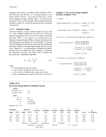
operation of the screen. According to Rex Chainbelt (1955), Example 5.1 Bar Screen Design (Adapted
later Rexnord, then Envirex, it is standard practice to use from Rex Chainbelt, 1955)
8mm 80 mm (5=16 in. 2 in.) bars for bars up to 1.83 m
(6 ft) in length or 95 mm 64 mm (3=8 in. 21=2 in.) bars for 1. Assume
bars up to 3.66 m (12 ft) in length. The freeboard allowance
3
should be at least 9 in. for the bar protrusion above maximum Q(max sewage flow) ¼ 0:176 m =s[¼4 mgd ¼ 4 1:547
sewage level. 3
¼ 6:2ft =s]
5.2.1.5 Hydraulic Design 3
Q(max storm flow) ¼ 0:308 m =s[¼7mgd ¼ 7 1:547
Velocities through a sewage treatment plant bar screen rack 3
¼ 10:8ft =s]
in a clean condition should not exceed 0.61 m=s(2 ft=s) for
normal sewage flows or 0.91 m=s(3 ft=s) for storm water flows
2. Net area, A n , of bar rack for sewage flow condition is
(Rexnord, 1955). A key concern is to minimize the carry
through of retained material. These velocities are the basis for
determining the gross channel area (see Example 5.1). In add- Q(max sewage flow)
A n (max sewage flow) ¼
ition, the headloss through the bar screen must be calculated to V s (max sewage flow)
determine whether or not appreciable backup will occur in the " 3 #
3
0:176 m =s 6:2ft =s
sewer. Equation 5.1 is recommended to calculate the headloss
3
¼ 0:61 m =s ¼ 2:0ft=s
through a bar screen (Rexnord, 1955). Example 5.1 illustrates
the calculation procedure and Table CD5.2 translates the 2 2
¼ 0:29 m [¼3:1ft ]
procedure into a spreadsheet algorithm.
3. Net area, A n , for storm flow condition is
2
2
1 v v c
s
0:7 2g
h L ¼ (5:1)
Q(max storm flow)
V s (max storm flow)
A n (max storm flow) ¼
where
" #
3
3
h L is the headloss across bar screen 0:308 m =s 10:8ft =s
v s is the velocity through the rack (m=s), (ft=s) ¼ 0:91 m=s ¼ 3:0ft=s
v c is the velocity in channel above rack (m=s), (ft=s)
2
2
2
2
g is the acceleration due to gravity (9.81 m=s ), (32.2 ft=s ) ¼ 0:34 m [¼3:6ft ]
TABLE CD5.2
Bar Screen Design Based on Hydraulic Criteria
Criteria
v(sewage) Š ¼ 0.61 m=s
v(storm) Š ¼ 0.91 m=s
Given
Q ¼ 4.0 mgd
Bars 51 mm deep
25 mm opening
8 mm bar width
Ratio(free area) ¼ 0.76
A A A A V V
Q(sewage) Q(storm)
(net=sew) (net=storm) (net=sew) (gross) (screen) (channel) h L
2
2
3
3
2
2
(mgd) (m =s) (mgd) (m =s) (m ) (m ) (m ) (m ) (m=s) (m=s) h L (m) (1=2 Plug) (m)
1.00 0.044 4.0 0.175 0.07 0.19 0.19 0.25 0.91 0.17 0.058 0.239
2.00 0.088 5.0 0.219 0.14 0.24 0.24 0.32 0.91 0.28 0.055 0.236
4.00 0.175 7.0 0.307 0.29 0.34 0.34 0.44 0.91 0.39 0.049 0.230
8.00 0.350 10.0 0.438 0.57 0.48 0.57 0.76 0.61 0.46 0.012 0.093
A(net=sew) ¼ Q=v(sewage) Channel area Q=A(gross)
2
2
A(net=storm) ¼ Q=v(storm) Max vel. ¼ (v s v c )=2g=:7
Select larger A