
Page 128 - Fundamentals of Water Treatment Unit Processes : Physical, Chemical, and Biological
P. 128
Screening 83
0.6 2.0
Comminutor Comminutor
d d d d
0.5 1 2 1 2
1.5
0.4
(d 1 –d 2 ) (m) 0.3 d =0 cm (d 1 –d 2 ) (ft) 1.0 d 2 =0 in
2
0.2
0.5
0.1
5 10 20 30 d =40 cm 2 4 8 12 d =16 in
2
2
0.0 0.0
0.0 0.1 0.2 0.3 0.4 0.5 0 5 10 15 20
3
3
(a) Q (m /s) (b) Q (ft /s)
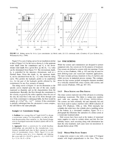
FIGURE 5.5 Rating curves for 16 in. Lyco comminutor. (a) Metric units, (b) U.S. customary units. (Courtesy of Lyco Systems, Inc.,
Williamsport, PA, c. 1969).
Figure 5.5 is a set of rating curves for an installation similar 5.4 FINE SCREENS
to that of Figure 5.4. For the curves shown, h 1 is the upstream
While bar screens and comminutors are designed to protect
water depth from the comminutor and h 2 is the down-
stream water depth. For a given flow, Q, the (h 2 h 1 ) value equipment only, fine screens are for the purpose of treatment.
Fine screens are defined as screens with size openings 12 mm
can be determined from Figure 5.5. The downstream depth,
(0.5 in.) or less (Pankratz, 1988, p. 167) and may be used for
h 2 , is controlled by the structures downstream, such as a
both drinking-water and wastewater treatment applications.
Parshall flume. From this depth, h 2 , the upstream depth,
The latter includes primary treatment in lieu of clarifiers and
h 1 can be calculated from the (h 2 h 1 ) value from the rating
solids recovery in industrial process streams. The configur-
curve. This permits the hydraulic profile to be established
ations for fine screens include rectangular elements mounted
(i.e., for the part of the hydraulic profile affected by the
on a vertically oriented belt, rotary screens, disk screens, and
comminutor) for any flow scenario of interest.
static screens (Pankratz, 1988, pp. 167–181).
The rating curves of Figure 5.5 are for illustration as the
specific curves depend upon the size of the unit, usually
expressed as diameter, and on the characteristics from the
manufacturer. Basically, the flow through the comminutor is 5.4.1 DRUM SCREENS AND DISK SCREENS
the velocity, as given by the orifice equation, times the area of The rotary screens represent one of the advances in screening
the slot; the total flow is the sum of the flows through each technology wastewater. The fabric is wedge-wire stainless
slot. If the comminutor is submerged fully, the flow would be steel with slot openings 0.25–2.5 mm (0.010–0.10 in.).
0.5
simply, Q ¼ C(2g) (h 2 h 1 ) 0.5 A(slots). If the comminutor The screens are both externally fed and internally fed and
is partially submerged then the calculation is more complex, have been used to replace clarifiers with a BOD reduction of
but still follows the same principle. about 35% (Pankratz, 1988, p. 168). With internally fed
cylinders the solids leave the cylinder after a tumbling action
Example 5.2 Comminutor Design at the bottom, in a dewatered condition. Figure 5.6 is a
photograph that illustrates the operation of a drum screen at
3
1. Problem: For a sewage flow of 7 mgd (10.8 ft =s), design a wastewater treatment plant.
a comminutor system. For this problem, in order to illus- Disk screens have been used at the intakes of municipal
trate the procedure, flow variation, i.e., the diurnal change water supplies in order to exclude debris and fish. For low
seen in municipal wastewater treatment plants will not be turbidity waters, such screening along with chlorination has
considered. been the only treatment; such cases were not uncommon in
2. Approach: Select a comminutor for which headloss decades before about 1990.
relationships are provided by the manufacturer. Lyco
Systems provided such data in their catalog for several
sizes of comminutors (Anon, 1969). Figure 5.5 is one 5.4.2 WEDGE-WIRE STATIC SCREENS
such headloss curve for a 16 in. diameter unit. Entering
3
the curve with Q ¼ 10.8 ft =s, gives (h 1 h 2 ) ¼ 0.65 ft for A wedge-wire screen is one with a wire made of V-shaped
h 2 ¼ 12 in. Or, h 1 ¼ 20 in. strands with length perpendicular to the flow. They have