
Page 127 - Fundamentals of Water Treatment Unit Processes : Physical, Chemical, and Biological
P. 127
82 Fundamentals of Water Treatment Unit Processes: Physical, Chemical, and Biological
The larger of the two net areas should be used, i.e., for This amount of headloss is not desirable because of
the case at hand, surges caused by removing the material on the rack,
and also because of resulting slower velocities in the
A n (max storm flow) > A n (max sewage flow), sewer, which permits the deposition of settleable mater-
ial. Therefore, the cleaning cycle should assure that
and therefore, such conditions do not occur.
2
2
A n ¼ 0:34 m [¼3:6ft ]
5.3 COMMINUTORS
4. The gross area is calculated as follows:
A comminutor is a bar screen with a cutting device aligned
First, select a rack consisting of 51 mm 8mm(2in.
5=16 in.) bars space to provide a clear opening of with the bar. The blades shred the retained material, usually
25 mm (1 in.). stringy items, allowing it to pass. In most installations the
The ratio of free area to gross area is
screens are circular in shape, although a rack may be used.
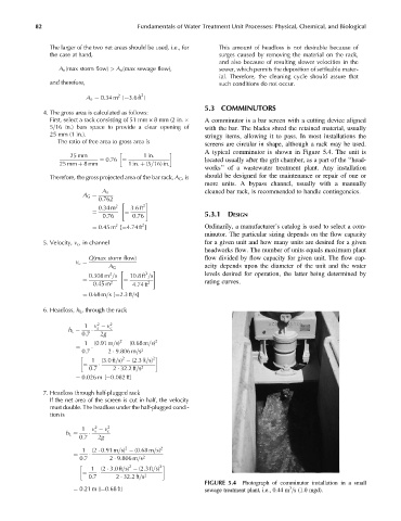
A typical comminutor is shown in Figure 5.4. The unit is
25 mm 1in:
located usually after the grit chamber, as a part of the ‘‘head-
25 mm þ 8mm 1in: þ (5=16) in:
¼ 0:76 ¼
works’’ of a wastewater treatment plant. Any installation
Therefore, the gross projected area of the bar rack, A G ,is should be designed for the maintenance or repair of one or
more units. A bypass channel, usually with a manually
cleaned bar rack, is recommended to handle contingencies.
A n
0:762
A G ¼
" 2 #
0:34 m 2 3:6ft
¼ ¼ 5.3.1 DESIGN
0:76 0:76
2
2
¼ 0:45 m [¼4:74 ft ] Ordinarily, a manufacturer’s catalog is used to select a com-
minutor. The particular sizing depends on the flow capacity
5. Velocity, v c , in channel for a given unit and how many units are desired for a given
headworks flow. The number of units equals maximum plant
Q(max storm flow) flow divided by flow capacity for given unit. The flow cap-
v c ¼
A G acity depends upon the diameter of the unit and the water
" 3 #
3
0:308 m =s 10:8ft =s levels desired for operation, the latter being determined by
0:45 m 4:74 ft
¼ 2 ¼ 2 rating curves.
¼ 0:68 m=s[¼2:3ft=s]
6. Headloss, h L , through the rack
2
1 v v 2
s c
h L ¼
0:7 2g
2
1 (0:91 m=s) (0:68 m=s) 2
0:7 2 9:806 m=s
¼ 2
2 2
1 (3:0ft=s) (2:3ft=s)
¼ 2
0:7 2 32:2ft=s
¼ 0:026 m [¼0:082 ft]
7. Headloss through half-plugged rack
If the net area of the screen is cut in half, the velocity
must double. The headloss under the half-plugged condi-
tion is
2
1 v v 2
s c
h L ¼
0:7 2g
2
1 (2 0:91 m=s) (0:68 m=s) 2
0:7 2 9:806 m=s
¼ 2
2 2
1 (2 3:0ft=s) (2:3ft=s)
0:7 2 32:2ft=s
¼ 2
FIGURE 5.4 Photograph of comminutor installation in a small
¼ 0:21 m [¼0:68 ft] sewage treatment plant, i.e., 0.44 m =s (1.0 mgd).
3