
Page 129 - Fundamentals of Water Treatment Unit Processes : Physical, Chemical, and Biological
P. 129
84 Fundamentals of Water Treatment Unit Processes: Physical, Chemical, and Biological
been used in mining since 1955, and for many years in food
processing and wastewater treatment (Wahl and Einhellig,
2000, p. 2, Wahl, 2001, p. 1). An evolution in the design,
introduced by patent in 1983, changed the orientation of the
individual wire strands such that the wire surface was
‘‘tilted’’ downstream at a slight angle; at the same time, the
functioning of the screen was changed (as explained subse-
(a) quently).
Figure 5.7a is a side-view schematic drawing as an instal-
lation might be configured and Figure 5.7b is a side-view
detail of the wire and flow and shows the ‘‘tilt’’ angle, f,of
the individual wires. Figure 5.8 is a photograph of an instal-
lation at Empire, Colorado, with a population of about 500,
located at its intake in a diversion structure at Mad Creek that
provides water to its slow sand filter.
The merit of the wedge-wire screen is that it is ‘‘self-
cleaning,’’ i.e., there is no accumulation of matter on the
(b) surface. The high velocity of water across the screen,
v(bypass), transports most debris away from the slot openings
FIGURE 5.6 Drum screen, internally fed, used in lieu of primary
to exit the screen; therefore, it is necessary that Q(bypass) 0.
clarifier. (a) Side view of drum. (b) Perspective view of drum. (Courtesy
The screens may be flat or concave-down with a radius
of Centennial Water and Sanitation District, Highlands Ranch, CO.)
of curvature 3–4 m. The hydraulic characteristics of
the screens have been investigated by the U.S. Bureau
of Reclamation in Denver (see Wahl, 1995, 2001; Wahl and
Acceleration plate Einhellig, 2001).
Q(inflow)
To expand on the self-cleaning feature of the screen, the
tangential flow or the water and debris across the face of
Wedge-wire screen the screen causes about 90% removal of the debris that is
50% of the screen wire spacing, i.e., its slot width. For
example, a 0.5 mm wire spacing will remove 90% of all
matter larger than 0.25 mm. This feature is further enhanced
by the fact that particles and debris have mass and momentum
Q(screen)
as they flow down the face of the screen and tend to continue
in the direction that they are moving. The abrupt change in
Q(bypass)
Outflow the fluid flow direction caused by the shearing action of
pipe the wires enhances the self-clean feature of the screen
(Weir, 2002).
(a)
ΔQ
S
φ
W
θ
(b)
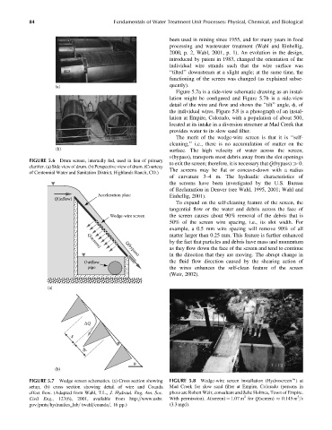
FIGURE 5.7 Wedge screen schematics. (a) Cross section showing FIGURE 5.8 Wedge-wire screen installation (Hydroscreene)at
setup, (b) cross section showing detail of wire and Coanda Mad Creek for slow sand filter at Empire, Colorado (persons in
effect flow. (Adapted from Wahl, T.L., J. Hydraul. Eng. Am. Soc. photo are Robert Weir, consultant and Julie Holmes, Town of Empire.
3
2
Civil Eng., 127(6), 2001, available from http:==www.usbr. With permission). A(screen) ¼ 1.07 m for Q(screen) 0.145 m =s
gov=pmts=hydraulics_lab= twahl=coanda=, 16 pp.) (3.3 mgd).