
Page 134 - Fundamentals of Water Treatment Unit Processes : Physical, Chemical, and Biological
P. 134
Screening 89
0.1 10 –2
60 μm outlier 60 μm
35 μm outlier 35 μm 21 μm
10 –3
6 μm
HLR (m 3 /m 2 /s) 74 μm K (m/s) 10 –4
0.01
21 μm
6 μm
–5
10
0.001
74 μm
Assumptions:
1 μm 10 –6 w=1.0 rpm
1 μm h L =0.3048 m
HLR=[K ω h 1/2
· · L ]
0.0001 10 –7
0.01 0.1 1 5 10 20 30 50 70 80 90 95 99 99.9 99.99 0.01 0.1 1 5 10 20 30 50 70 80 90 95 99 99.9 99.99
(a) Percent (b) Percent
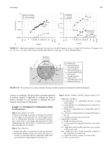
FIGURE 5.9 Microscreen parameter frequencies by screen size. (a) HLR frequency for h L ¼ 0.1 rad=s. (b) Coefficient, K, frequency for
h L ¼ 0.3 m, v ¼ 0.1 rad=s. (From Envirex, Envirex Data Sheet 315-3.201, pp. 1–3, 1982. With permission.)
Backwash
h L =headloss (m)
C o =conc of particles in
ω
3
h L feed water (kg m )
C=conc of particles/
+ v after screening (kg/m )
3
ω=rotation velocity (rad/s)
Q v v=flow velocity
through mat (m/s)
Q =angle of screen
v
accumulating mat (rad)
v
v x= thickness of mat (m)
x
FIGURE 5.10 Microscreen cross-section schematic showing variables of interest in mathematical model development.
exercise, as a challenge. The idea is that a systematic approach Step 3: Identify variables, aided by diagram (Figure 5.10)
to problem analysis is applicable to virtually any kind of
1. Dependent variables:
process. Example 5.3 was intended to illustrate this tenet
C ¼ concentration of suspended particles leaving
using the microscreen for illustration. 3
screen (kg=m )
C r ¼ concentration of suspended particles removed by
3
Example 5.3 Development of Mathematical Model screen (kg=m )
for Microscreen X ¼ thickness of deposited mat of suspended matter at
any Q (m)
Step 1: State purpose of model X M ¼ thickness of deposited mat of suspended matter at
A theory in screening, in general, is lacking. The problem Q M (m)
is seen largely as the application of a technology to prac- h L ¼ headloss across screen and mat (m)
tice. A mathematical depiction of microscreen perform- 2. Independent variables:
ance could serve to aid design and operation by better L ¼ length of microscreen (m)
understanding the mechanisms of microscreen perform- C o ¼ concentration of suspended particles in raw water
3
ance, thus the role of variables. (kg=m )
Q ¼ angle from initial outside water line to any location
Step 2: State objectives
on the screen (rad)
1. Explore the utility of mathematical relations obtained. Q M ¼ angle from initial outside water line to final out-
2. Determine headloss across the screen and mat as a side water line on screen (rad)
function of rotational velocity, suspended solids load- v ¼ rotational velocity, omega, of screen (rad=s)
3
ing, hydraulic loading, degree of cleaning, etc. Q ¼ flow to screen (m =s)