
Page 226 - Fundamentals of Water Treatment Unit Processes : Physical, Chemical, and Biological
P. 226
Flotation 181
with 0.0 r 0.5 (r ¼ 0 indicates that the full flow, Q, passed
through the saturator). TABLE 8.5
List of Variables for Pilot Plant Study
8.4.1.2 Flotation for Sludge Thickening
Variables
In thickening, the solids loading rate is more important than
SOR (Haarhoff and van Vuuren, 1995, p. 209). Guidelines for Unit Process Dependent Independent
2
solids loading are (1) without coagulation, 2.0–6.0 kg=m =h; Rapid mix Zeta potential u, G
2
and (2) with coagulants, 6.0–12.0 kg=m =h. Metal coagulant selection
Coagulant dosage
8.4.1.3 Air-to-Solids Ratio Polymer selection
The air-to-solids ratio (i.e., A=S) is an empirical parameter Polymer dosage
defined as the ratio of the mass fluxes of air and solids, Flocculation Floc size N(compartments)
respectively, where A is the mass flux of air from the Floc strength u
saturator, and S is the mass flux of solids entering the ‘‘contact C(particles) out P=V
zone,’’ i.e., Saturator C(O 2 ) e R, P(sat), HLR, K L a
Packing type
A ¼ R C(saturator)(kg air in flow from saturator=s) L(packing)
Pump sizing (head, flow)
S ¼ Q C(floc)(kg solids=s)
Compressor sizing
Flotation C(particles) e Floc size
Thus, A=S ¼ R C(saturator)=Q C(floc) with units (kg air=kg Floc strength
solids). As stated in Section 8.1.2, the parameter was used first C(particles) in
by Eckenfelder et al. (1958, p. 257) who gave limits as, 0.03 C(O 2 ) sat
A=S 0.10 kg air=kg solids. They also presented empirical R
plots showing that increasing A=S results in increasing percent Q
solids in the float layer. Matsui et al. (1998, p. 16) reviewed the v o
use of the A=S parameter by Eckenfelder et al., and recom- Tank design
mended A=S 0.01, which ensures an excess of air bubbles
Notes: (1) In lieu of ‘‘air,’’ dissolvedoxygenmayserve as a
relative to the volume needed to float the floc particles. The A=S
surrogate since its concentration may be measured
ratio is similar in concept to the bubble-to-particle ratio.
easily by instrument of by the ‘‘Winkler’’ method (see
Standard Methods).
8.4.2 PILOT PLANTS
A pilot plant can address design issues such as flocculation
turbulence intensity, basin sizing, and saturator design. Oper- dependent and independent variables for the respective unit
ation questions involve selection of coagulants and dosages, processes. The dependent variables include those that are the
including polymers, sensitivity to flow variation, airflow outcome of change in the independent variables. A dependent
required, and recycle flow. variable for one unit process may serve as an independent
variable for another.
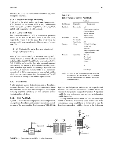
8.4.2.1 Pilot Plant Study Looking at the variables in Table 8.5, it is clear that a large
Figure 8.12 shows sketches of equipment for subunit processes, number of functional relationships could be involved. To be
i.e., rapid mix, flocculation, and saturator, respectively, indicat- economical, a study would have to be limited to only the
ing some of the variables of the flotation process. Table 8.5 lists dependent=independent variables relevant to the design and
P
R, C a
P(sat)
ω ω
Q(alum) Saturator
Q Q Q(air)
Q(polymer)
C
d(floc)
Q Rapid Q C(floc)
mix R
Flocculation C(saturator)
FIGURE 8.12 Sketch showing variables for pilot plant study.