
Page 228 - Fundamentals of Water Treatment Unit Processes : Physical, Chemical, and Biological
P. 228
Flotation 183
commissioning the new facilities was 12 months of perform- The DAF tank requires a nozzle so that the gas precipita-
ance testing for optimization of operation. tion occurs before mixing with the feed flow. The feed flow
requires rapid-mix=coagulation and flocculation prior to
entering the contact zone. Once the floc–bubble attachments
8.4.4 EQUIPMENT
occur and the agglomerates float to the surface, the float so
Figure 8.1 indicates major components of the DAF technol- formed must be removed by a skimmer blade assembly that
ogy. Supporting appurtenances are not shown and are transfers the solids to a collection trough. The effluent flow is
reviewed here. First, the recycle line requires flow measure- collected near the bottom of the tank with a portion becoming
ment and a valve for flow control, as well as a pump for recycle flow.
pressurizing the saturator. Dissolved oxygen (DO) probes Usually, for small systems, designs provide a complete
should be located in the influent and effluent streams, with ‘‘package’’ with the necessary appurtenances. Table 8.6 gives
DO serving as a surrogate for dissolved air. Dissolved nitro- dimensions of several package plants from one manufacturer
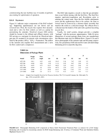
gen may be assumed to be present with concentration calcu- that illustrates tank sizes for different flows. Figure 8.13a and b
lated by the product, H(N 2 ) X(N 2 ) P(saturator). The airflow shows photographs of the saturator tank and the pump, respect-
to the saturator also requires flow measurement and a valve ively, for a proprietary DAF unit used for waste-activated sludge
for flow control and a compressor. thickening prior to anaerobic digestion.
TABLE 8.6
Dimensions of Package Plants
L W D
Design Flow
3
Model (m =s) (mgd) (m) (ft) (m) (ft) (m) (ft)
LFT-250 0.011 0.25 6.83 22.42 2.34 7.67 2.90 9.5
LFT-500 0.022 0.50 9.55 31.33 2.95 9.67 2.90 9.5
LFT-750 0.033 0.75 12.27 40.25 3.25 10.67 2.90 9.5
LFT-1000 0.044 1.0 13.64 44.75 3.56 11.67 3.35 11.0
LFT-1500 0.066 1.5 18.95 62.17 3.86 12.67 3.51 11.5
LFT-2000 0.088 2.0 21.72 71.25 4.32 14.17 3.51 11.5
Source: Adapted from Leopold, Dissolved Air Flotation, brochure, The F. B. Leopold Company, Inc. Zelienople, PA,
8pp., 1996 (revised 2001, 2003).
(a) (b)
FIGURE 8.13 Photographs illustrating DAF components at Marcy Gulch Wastewater Treatment Plant: (a) saturator for a DAF sludge-
thickening unit; (b) pump for pressurizing saturator for DAF sludge-thickening unit. (Courtesy of Centennial Water and Sanitation District,
Highlands Ranch, CO.)