
Page 223 - Fundamentals of Water Treatment Unit Processes : Physical, Chemical, and Biological
P. 223
178 Fundamentals of Water Treatment Unit Processes: Physical, Chemical, and Biological
Solution C(saturator) is the mass concentration of dissolved gas
The calculation is by Equation 8.18 leaving saturator in recycle flow, R, then flowing
through the manifold and nozzles; the ‘‘excess’’ concen-
3
C r ¼ N p B r(air) (pd b =6) (8:18) trations of the gases are precipitated in the expansion
3
¼ (1:2 10 10 particles=m water) part of the nozzle and then enter the contact zone of the
3
flotation basin (kg gas=m water) as bubbles
3
(1:204 kg air=m gas (10 bubbles=particle)
C a is the mass concentration of dissolved gas leaving
3
p (40 10 6 m=bubble) =6 contact zone and then the separation zone, being trans-
3
¼ 0:0048 kg air=m water ported in the flow, (Q þ R), which also leaves the basin
3
(kg gas=m )
Comments C r is the mass concentration of dissolved gas precipitated
A spreadsheet would facilitate computations. as bubbles in the expansion part of the nozzles, which
then enter the contact zone, after which they rise as
bubbles and bubble–particle agglomerates in the separ-
8.3.5 MATERIALS BALANCE FOR DISSOLVED GAS
ation zone, being transported from the contact zone in
3
IN FLOTATION BASIN the combined flow, (Q þ R) (kg gas=m )
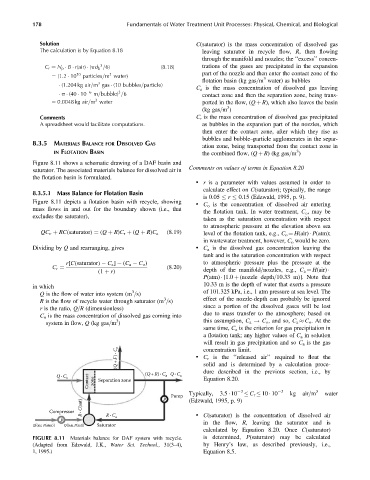
Figure 8.11 shows a schematic drawing of a DAF basin and
Comments on values of terms in Equation 8.20
saturator. The associated materials balance for dissolved air in
the flotation basin is formulated.
. r is a parameter with values assumed in order to
calculate effect on C(saturator); typically, the range
8.3.5.1 Mass Balance for Flotation Basin
is 0.05 r 0.15 (Edzwald, 1995, p. 9).
Figure 8.11 depicts a flotation basin with recycle, showing . C o is the concentration of dissolved air entering
mass flows in and out for the boundary shown (i.e., that
the flotation tank. In water treatment, C o , may be
excludes the saturator),
taken as the saturation concentration with respect
to atmospheric pressure at the elevation above sea
QC o þ RC(saturator) ¼ (Q þ R)C r þ (Q þ R)C a (8:19) level of the flotation tank, e.g., C o ¼ H(air) P(atm);
in wastewater treatment, however, C o would be zero.
Dividing by Q and rearranging, gives . C a is the dissolved gas concentration leaving the
tank and is the saturation concentration with respect
r[C(saturator) C a ] (C a C o ) to atmospheric pressure plus the pressure at the
(8:20)
(1 þ r) depth of the manifold=nozzles, e.g., C a ¼ H(air)
C r ¼
P(atm) [1.0 þ (nozzle depth=10.33 m)]. Note that
10.33 m is the depth of water that exerts a pressure
in which
3
Q is the flow of water into system (m =s) of 101.325 kPa, i.e., 1 atm pressure at sea level. The
3
R is the flow of recycle water through saturator (m =s) effect of the nozzle-depth can probably be ignored
since a portion of the dissolved gases will be lost
r is the ratio, Q=R (dimensionless)
due to mass transfer to the atmosphere; based on
C o is the mass concentration of dissolved gas coming into
3
system in flow, Q (kg gas=m ) this assumption, C a ! C o , and so, C a C o . At the
same time, C a is the criterion for gas precipitation in
a flotation tank; any higher values of C a in solution
will result in gas precipitation and so C a is the gas
(Q + F ) · C r . C r is the ‘‘released air’’ required to float the
concentration limit.
solid and is determined by a calculation proce-
Contact zone Separation zone Equation 8.20.
Q · C o (Q+R) · C a Q · C a dure described in the previous section, i.e., by
Typically, 3.5 10 3 C r 10 10 3 kg air=m 3 water
Pump (Edzwald, 1995, p. 9)
P
R · C(sat)
Compressor R · C . C(saturator) is the concentration of dissolved air
P a
Q[(air, P(atm)] Q[(air, P(sat)] Saturator in the flow, R, leaving the saturator and is
calculated by Equation 8.20. Once C(saturator)
FIGURE 8.11 Materials balance for DAF system with recycle. is determined, P(saturator) may be calculated
(Adapted from Edzwald, J.K., Water Sci. Technol., 31(3–4), by Henry’s law, as described previously, i.e.,
1, 1995.) Equation 8.5.