
Page 286 - Fundamentals of Water Treatment Unit Processes : Physical, Chemical, and Biological
P. 286
Mixing 241
3
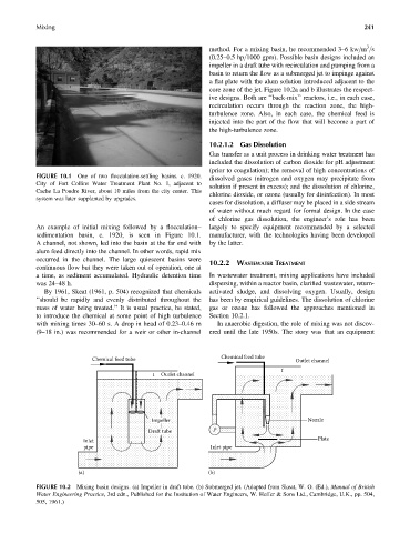
method. For a mixing basin, he recommended 3–6kw=m =s
(0.25–0.5 hp=1000 gpm). Possible basin designs included an
impeller in a draft tube with recirculation and pumping from a
basin to return the flow as a submerged jet to impinge against
a flat plate with the alum solution introduced adjacent to the
core zone of the jet. Figure 10.2a and b illustrates the respect-
ive designs. Both are ‘‘back-mix’’ reactors, i.e., in each case,
recirculation occurs through the reaction zone, the high-
turbulence zone. Also, in each case, the chemical feed is
injected into the part of the flow that will become a part of
the high-turbulence zone.
10.2.1.2 Gas Dissolution
Gas transfer as a unit process in drinking water treatment has
included the dissolution of carbon dioxide for pH adjustment
(prior to coagulation); the removal of high concentrations of
FIGURE 10.1 One of two flocculation-settling basins. c. 1920.
dissolved gases (nitrogen and oxygen may precipitate from
City of Fort Collins Water Treatment Plant No. 1, adjacent to
solution if present in excess); and the dissolution of chlorine,
Cache La Poudre River, about 10 miles from the city center. This
chlorine dioxide, or ozone (usually for disinfection). In most
system was later supplanted by upgrades.
cases for dissolution, a diffuser may be placed in a side stream
of water without much regard for formal design. In the case
of chlorine gas dissolution, the engineer’s role has been
An example of initial mixing followed by a flocculation– largely to specify equipment recommended by a selected
sedimentation basin, c. 1920, is seen in Figure 10.1. manufacturer, with the technologies having been developed
A channel, not shown, led into the basin at the far end with by the latter.
alum feed directly into the channel. In other words, rapid mix
occurred in the channel. The large quiescent basins were
10.2.2 WASTEWATER TREATMENT
continuous flow but they were taken out of operation, one at
a time, as sediment accumulated. Hydraulic detention time In wastewater treatment, mixing applications have included
was 24–48 h. dispersing, within a reactor basin, clarified wastewater, return-
By 1961, Skeat (1961, p. 504) recognized that chemicals activated sludge, and dissolving oxygen. Usually, design
‘‘should be rapidly and evenly distributed throughout the has been by empirical guidelines. The dissolution of chlorine
mass of water being treated.’’ It is usual practice, he stated, gas or ozone has followed the approaches mentioned in
to introduce the chemical at some point of high turbulence Section 10.2.1.
with mixing times 30–60 s. A drop in head of 0.23–0.46 m In anaerobic digestion, the role of mixing was not discov-
(9–18 in.) was recommended for a weir or other in-channel ered until the late 1950s. The story was that an equipment
Chemical feed tube Chemical feed tube Outlet channel
t
t Outlet channel
Impeller Nozzle
Draft tube P
Plate
Inlet
pipe Inlet pipe
(a) (b)
FIGURE 10.2 Mixing basin designs. (a) Impeller in draft tube. (b) Submerged jet. (Adapted from Skeat, W. O. (Ed.), Manual of British
Water Engineering Practice, 3rd edn., Published for the Institution of Water Engineers, W. Heffer & Sons Ltd., Cambridge, U.K., pp. 504,
505, 1961.)