
Page 290 - Fundamentals of Water Treatment Unit Processes : Physical, Chemical, and Biological
P. 290
Mixing 245
(a) (b )
(b)
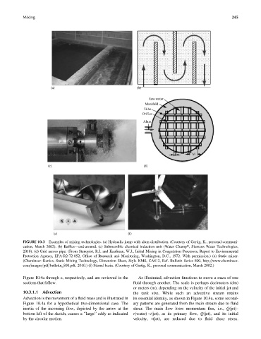
Raw water
Manifold
Tube
Orifice
Alum
d M
(c) (d)
(e) (f)
FIGURE 10.3 Examples of mixing technologies. (a) Hydraulic jump with alum distribution. (Courtesy of Gertig, K., personal communi-
cation, March 2002). (b) Baffles—end-around. (c) Submersible chemical induction unit (Water Champt, Siemens Water Technologies,
2010). (d) Grid across pipe. (From Stenquist, R.J. and Kaufman, W.J., Initial Mixing in Coagulation Processes, Report to Environmental
Protection Agency, EPA-R2-72-052, Office of Research and Monitoring, Washington, D.C., 1972. With permission.) (e) Static mixer.
(Chemineer–Kenics, Static Mixing Technology, Dimension Sheet, Style KMS, CA812, Ref. Bulletin Series 800, http:==www.chemineer.
com=images=pdf=bulletin_800.pdf, 2010.) (f) Stirred basin. (Courtesy of Gertig, K., personal communication, March 2002.)
Figure 10.4a through c, respectively, and are reviewed in the As illustrated, advection functions to move a mass of one
sections that follow. fluid through another. The scale is perhaps decimeters (dm)
or meters (m), depending on the velocity of the initial jet and
10.3.1.1 Advection the tank size. While such an advective stream retains
Advection is the movement of a fluid mass and is illustrated in its essential identity, as shown in Figure 10.4a, some second-
Figure 10.4a for a hypothetical two-dimensional case. The ary patterns are generated from the main stream due to fluid
inertia of the incoming flow, depicted by the arrow at the shear. The main flow loses momentum flux, i.e., Q(jet)
bottom left of the sketch, causes a ‘‘large’’ eddy as indicated r(water) v(jet), as its primary flow, Q(jet), and its initial
by the circular motion. velocity, v(jet), are reduced due to fluid shear stress.