Page 293 - Fundamentals of Water Treatment Unit Processes : Physical, Chemical, and Biological
P. 293

248                            Fundamentals of Water Treatment Unit Processes: Physical, Chemical, and Biological


                                                                    formation due to flow past three shapes: (a) a cylin-
                                                                    der, (b) multiple airfoils, and (c) an inclined flat
                                                                                                       5
                                                                    plate. For each of the three cases, R   10 . Figure
                                                                    10.8a shows an initial eddy about the size of the
                                                                    cylinder and just behind it the eddy grows in size as
                                                                    it is advected downstream. In Figure 10.8b multiple
                                                                    airfoils cause the same effect but downstream the
                                                                    adjacent eddies impinge against each other. In
                                                                    Figure 10.8c the inclined flat plate causes separation
                                                                    on the underside with intense mixing. As noted,
                                                                    the fate of the eddies is an ‘‘energy-cascade’’ with
                                                                    an eventual dissipation of the energy as viscous
            (a)                                                     forces and heat (Hanson and Cleasby, 1990;
                                                                    Hanson, 2001).
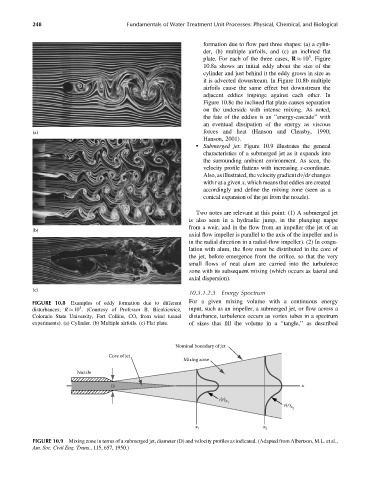
                                                                  . Submerged jet: Figure 10.9 illustrates the general
                                                                    characteristics of a submerged jet as it expands into
                                                                    the surrounding ambient environment. As seen, the
                                                                    velocity profile flattens with increasing x-coordinate.
                                                                    Also, as illustrated, the velocity gradient dv=dr changes
                                                                    with r at a given x, which means that eddies are created
                                                                    accordingly and define the mixing zone (seen as a
                                                                    conical expansion of the jet from the nozzle).

                                                                  Two notes are relevant at this point: (1) A submerged jet
                                                               is also seen in a hydraulic jump, in the plunging nappe
                                                               from a weir, and in the flow from an impeller (the jet of an
            (b)
                                                               axial flow impeller is parallel to the axis of the impeller and is
                                                               in the radial direction in a radial-flow impeller). (2) In coagu-
                                                               lation with alum, the flow must be distributed in the core of
                                                               the jet, before emergence from the orifice, so that the very
                                                               small flows of neat alum are carried into the turbulence
                                                               zone with its subsequent mixing (which occurs as lateral and
                                                               axial dispersion).
            (c)
                                                               10.3.1.2.3  Energy Spectrum
            FIGURE 10.8  Examples of eddy formation due to different  For a given mixing volume with a continuous energy
                           5
            disturbances; R   10 . (Courtesy of Professor B. Bienkiewicz,  input, such as an impeller, a submerged jet, or flow across a
            Colorado State University, Fort Collins, CO, from wind tunnel  disturbance, turbulence occurs as vortex tubes in a spectrum
            experiments). (a) Cylinder. (b) Multiple airfoils. (c) Flat plate.  of sizes that fill the volume in a ‘‘tangle,’’ as described


                                                           Nominal boundary of jet
                                     Core of jet
                                                             Mixing zone
                          Nozzle

                                      D                                                             x

                                                                         v(r) x
                                                                            1
                                                                                              v(r) x
                                                                                                 2
                                                                 x 1                    x 2

            FIGURE 10.9  Mixing zone in terms of a submerged jet, diameter (D) and velocity profiles as indicated. (Adapted from Albertson, M.L. et al.,
            Am. Soc. Civil Eng. Trans., 115, 657, 1950.)
   288   289   290   291   292   293   294   295   296   297   298