
Page 322 - Fundamentals of Water Treatment Unit Processes : Physical, Chemical, and Biological
P. 322
Mixing 277
5
10.4.4.3 Static Mixers ents become 32 (16 dark and 16 light), i.e., 2 . With a sixth
Static mixers comprise proprietary ‘‘elements’’ that are element, the 32 tagged elements become 64 (32 dark and
6
inserted in a pipe to cause a sequence of flow bifurcations. 32 light), i.e., 2 . At this point, any two of the different tinted
In water treatment, static mixers may be used for the same fluid elements are not distinguishable. If the flow should be
purposes as for other mixers, e.g., flash mixing for coagula- turbulent, and we may assume that in most cases the Reynolds
tion, pH control, blending a powdered activated carbon with number is high enough such that turbulent mixing occurs
raw water, chlorine or ozone dissolution, blending a flocculent within each element, mixing would be virtually complete at
aid with coagulated water prior to flocculation, blending of the end of the second or third element.
nutrients with raw wastewater prior to biological treatment,
10.4.4.3.2 Headloss
and blending a polymer with dilution water prior to use as a
coagulant aid (Mutsakis and Rader, 1986). The headloss from a static mixer is given by the same
relationship as for pipe friction (Amirtharajah et al., 2001,
10.4.4.3.1 Mixing with Static Mixers p. 37), i.e.,
A variety of proprietary forms have been fabricated for in-
pipe static mixers. Figure 10.26 shows a Kenicse static mixer L(static mixer) v(pipe) 2
h L (static mixer) ¼ f(static mixer)
with elements configured as helical blades placed in a 51 mm d(pipe) 2g
(2 in.) tube; the ridges of successive blades are orthogonal. (10:45)
A flow bifurcation occurs at the beginning of each element;
the twist in the blade causes fluid rotation first clockwise and where
then counterclockwise at the edge of the next element. h L (static mixer) is the headloss across static-mixer elem-
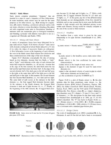
Figure 10.27 illustrates conceptually the idea of mixing ents (m)
based on five elements. Assume that two fluids, a ‘‘dark’’ f(static mixer) is the loss coefficient for static mixer
and a ‘‘light,’’ each bifurcate at the edge of each element but (dimensionless)
retain their respective identities, i.e., do not mix. Assume that L(static mixer) is the length of static mixer (m)
at the edge of the first element, the dark fluid enters the top d(pipe) is the diameter of pipe for used for static-mixer
half and the light fluid enters the lower half. At the edge of the elements (m)
second element, half of the dark goes to the left and half goes v(pipe) is the calculated velocity of water in pipe in which
to the right; at the same time, half of the light goes to the left static-mixer elements are located (m=s)
2
and half goes to the right. In this manner, the second element g is the acceleration of gravity (9.806650 m=s )
has four discrete fluid identities, i.e., two dark and two light.
The same kind of split occurs at the entrance to the third Figure 10.28 is a plot of f(static mixer) vs. R; the plot
element, i.e., the four tagged fluid elements become eight. includes data for three proprietary static mixers, i.e., the
At the entrance to the fourth element, the 8-tagged fluid Chemineer-Kenics KMS helical (Chemineer, Dayton, OH,
4
elements (4 dark and 4 light) become 16, i.e., 2 . Finally, at 2002); the Sulzer ChemTech SMV (Koch-Glitsch, Wichita,
the beginning of the fifth element, the 16 tagged fluid elem- Kansas; Koch, 2002); and the TAH spiral (TAH Industries,
Robbinsville, New Jersey), where R ¼ r v(pipe) d(pipe)=m;
pipe diameters were 25 < d(pipe) < 51 mm (1–2 in.), and 2
(# elements) 6. The data points for the three static mixers
(as obtained from Amirtharajah et al. 2001, pp. 37, 61–63)
plotted coincident. The ‘‘f’’ loss factor in Figure 10.28, i.e.,
1.5 f(static mixer) 1.0 for 2000 R 30,000, compares
with f(pipe) 0.06 for R 2000, which is 15–20 times lower,
but is consistent with a standard pipe-friction plot.
10.4.4.3.3 Design Criteria
FIGURE 10.26 Static mixer in 25 mm line for 76 L=min (20 gpm) The work of Amirtharajah et al. (2001) considered R, G, h L ,
pilot plant (1995 dwh). #elements, u, and Gu but did not find a basis to recommend
Elements 1 2 3 4 5
Graphic
Bifurcations 2 4 8 16 32
FIGURE 10.27 Illustration of effect of bifurcations. (Adapted from Avalosse, T. and Crochet, M.J., AIChE J., 43(3), 589, 1997b.)