
Page 317 - Fundamentals of Water Treatment Unit Processes : Physical, Chemical, and Biological
P. 317
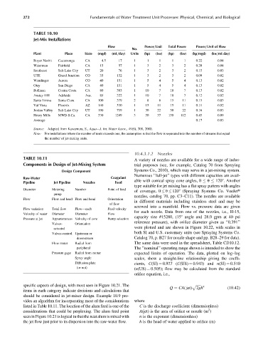
272                            Fundamentals of Water Treatment Unit Processes: Physical, Chemical, and Biological


                 TABLE 10.10
                 Jet-Mix Installations
                                                   Flow             Power=Unit  Total Power  Power=Unit of Flow
                                                              No.
                 Plant         Place    State  (mgd)  (mL=day)  Units  (hp)  (kw)  (hp)  (kw)  (hp=mgd)  (kw=mL day)
                 Royer Nesbit  Cucamonga  CA    4.5     17     1     1     1     1    1     0.22      0.04
                 Waterman   Fairfield     CA    15       57     1     3     2     3    2     0.20      0.04
                 Southeast  Salt Lake City  UT  20      76     1     3     2     3    2     0.15      0.03
                 UTE        Grand Junction  CO  35     132     1     3     2     3    2     0.09      0.02
                 Wemlinger  Aurora       CO    40      151     1     5     4     5    4     0.13      0.02
                 Otay       San Diego    CA    40      151     1     5     4     5    4     0.13      0.02
                 Bollman    Contra Costa  CA   80      303     1    10     7    10    7     0.13      0.02
                 Anstay Hill  Adelaide   Aus.  85      322     1    10     7    10    7     0.12      0.02
                 Santa Teresa  Santa Clara  CA  100    379     2     8     6    15   11     0.15      0.03
                 Val Vista  Phoenix      AZ   140      530     1    15    11    15   11     0.11      0.02
                 Jordan Valley  Salt Lake City  UT  190  719   1    30    22    30   22     0.16      0.03
                 Henry Mills  MWD-S.Ca.  CA   330     1249     3    50    37   150   112    0.45      0.09
                 Average                                                                    0.17      0.03

                 Source: Adapted from Kawamura, S., Aqua—J. Int. Water Assoc., 49(6), 309, 2000.
                 Note: For installations where the number of units exceeds one, the assumption is that the flow is separated into the number of streams that equal
                      the number of jet-mixing units.


                                                               10.4.3.1.2  Nozzles
            TABLE 10.11
                                                               A variety of nozzles are available for a wide range of indus-
            Components in Design of Jet-Mixing System          trial purposes (see, for example, Catalog 70 from Spraying
                              Design Component                 Systems Co., 2010), which may serve in a jet-mixing system.
                                                               Numerous ‘‘full-jet’’ types with different capacities are avail-
            Raw-Water                               Coagulant
            Pipeline      Jet Pipeline  Nozzles       Feed     able with conical spray cone angles, 0   u   1208. Another
                                                               type suitable for jet mixing has a flat spray pattern with angles
            Diameter     Metering   Number         Point of feed
                                                               of coverage, 0   u   1208 (Spraying Systems Co. VeeJett
                          pump
                                                               nozzles, catalog 70, pp. C3–C11). The nozzles are available
            Flow         Flow and head Flow and head  Orientation
                                                               in different materials including stainless steel and may be
                                                    of flow
                                                               screwed into a manifold. Flow vs. pressure data are given
            Flow variation  Total flow  Flow—each   Feed velocity
                                                               for each nozzle. Data from one of the nozzles, i.e., H-15,
            Velocity of water  Diameter  Diameter  Flow
                                                               capacity size #15280, (158 angle and 28.0 gpm at 40 psi
            Pressure at jet  Appurtenances Velocity of core  Pump selection
                                                               reference pressure), with orifice diameter given as ‘‘0.391’’
                         Valves-    Orientation
                                                               were plotted and are shown in Figure 10.22, with scales in
                          actuated
                         Valves-control Upstream or            both SI and U.S. customary units (see Spraying Systems Co.
                                     downstream                Catalog 70, p. B27 for nozzle shape and pp. B28–29 for data).
                         Flow meter  Radial from               The same data were used in the spreadsheet, Table CD10.12.
                                     peripheral                The ‘‘nominal’’ operating range shown is intended to show the
                         Pressure gage  Radial from center     expected limits of operation. The data, plotted on log–log
                                    Spray angle                scales, show a straight-line relationship giving the coeffi-
                                    Diffusion plate            cients, C(SI) ¼ 0.927 (C(US) ¼ 0.943) and n(SI) ¼ 0.510
                                     (or not)                  (n(US) ¼ 0.505); flow may be calculated from the standard
                                                               orifice equation, i.e.,

            specific aspects of design, with most seen in Figure 10.21. The                p ffiffiffiffiffi  n
                                                                                Q ¼ CA( jet)  2gh         (10:42)
            items in each category indicate decisions and calculations that
            should be considered in jet-mixer design. Example 10.9 pro-
            vides an algorithm for incorporating most of the considerations  where
            listed in Table 10.11. The location of the alum feed is one of the  C is the discharge coefficient (dimensionless)
                                                                                                 2
            considerations that could be perplexing. The alum feed point  A(jet) is the area of orifice or nozzle (m )
            seen in Figure 10.21 is logical in that the neat alum is mixed with  n is the exponent (dimensionless)
            the jet flow just prior to its dispersion into the raw-water flow.  h is the head of water applied to orifice (m)