
Page 316 - Fundamentals of Water Treatment Unit Processes : Physical, Chemical, and Biological
P. 316
Mixing 271
units, power of each, and power per unit of flow. The compil- 10.4.3.1 Flash Mixing by Submerged Jets
ation is indicative of the range in designs for flash-mix instal- The purpose of ‘‘flash-mixing’’ is to disperse coagulants, e.g.,
lations and is given for reference. For comparison, 0.05–0.2 alum, within 1–2 s throughout the raw-water flow. The sub-
kw=mLd (0.25–1hp=mgd) was recommended by ASCE- merged jet has the two key elements needed to accomplish this
AWWA (1997) as reported by Kawamura (2000, p. 308). task, i.e., advection and turbulence. Jet mixing and wake mix-
ing are the only technologies that may approach this mixing
ideal. Guidelines for jet design were given initially by Chao and
10.4.3 JET MIXERS
Stone (1979) with later amplification by Kawamura (1991,
A ‘‘jet’’ is a high-velocity flow of a given fluid. A ‘‘submerged 2000). In jet mixing, the alum is injected into the carrier water
jet’’ discharges into a fluid medium and is characterized by just prior to its dispersion in the main flow of raw water or
significant penetration, with its energy being dissipated by sometimes at the point of emergence of the jet flow.
turbulence. A jet mixer comprises one or more nozzles that Data compiled by Kawamura (2000, p. 309) are shown in
emit a high-velocity flow into a water medium, as illustrated Table 10.10 for 12 installations giving flow, number of units,
in Figure 10.7b. power per unit, total power, and power per unit of flow. The
Applications of jet mixing (common to other kinds power data are for that expended by electric motors rather
of mixing as well) include coagulation, disinfection, gas than by the jets. The actual power imparted to the jets may be
bubble dispersion, mixing within anaerobic reactors, etc. determined by placing a flow meter and a pressure gage in the
The jet-mixing technology has developed since about 1980 jet pipeline and another pressure gage in the pipeline, i.e.,
(see, for example, initial papers by Kawamura, 1976, p. 332; P(jet) ¼ Q (rg) Dh; using a motor efficiency of 0.7 and
Amirtharajah, 1979, p. 137; Chao and Stone, 1979) and seems allowing for headloss in the jet pipeline, the power consumed
to have become a favored method of ‘‘flash-mixing,’’ espe- at by jet-induced turbulence would be perhaps 0.7 fraction of
cially during the 1990s, with about 40 installations counted to the values given. Comparing values for power expended per
Year 2000 in the United States and Australia (Kawamura, unit of flow in Tables 10.9 and 10.10, lower values are seen
2000, p. 307). The advantages of jet mixing include simplicity for the jet mixing (these are motor power in each case).
such as no moving parts (except for a pump), low capital cost,
reliability, and effectiveness. A disadvantage is the possible 10.4.3.1.1 Design Components
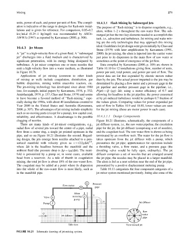
clogging of nozzles. Figure 10.21 illustrates, schematically, the components of a
There are many kinds of jet-mixer configurations, e.g., jet-diffuser system, i.e., the raw-water pipeline, the circulation
radial flow of several jets toward the center of a pipe, radial pipe for the jet, the jet diffuser (comprising a set of nozzles),
flow from a center ring, a single jet pointed upstream in the and the coagulant feed. The raw-water flow is shown as being
pipe, and so on Figure 10.21 illustrates the second. Regard- terminated by an overflow weir. The water for the jet flow is
ing design, the jets emerge from nozzles attached to a pres- taken upstream from the jet diffuser with a pump, which
0.5
surized manifold with velocity given as v ¼ C(2gDh) , pressurizes the jet pipe; appurtenances for operation include
where Dh is the headloss between the manifold and the a throttling valve, a flow meter, and a pressure gage (the
ambient fluid (the pressure drop is Dp ¼ (rg)Dh). The mani- throttling valve would be fully open, ordinarily). The jet
fold is pressurized by a pump or, in some cases, available diffuser comprises a set of nozzles that are arranged around
head from a reservoir. As a rule of thumb in coagulation the jet pipe; the nozzles may be placed in a larger manifold.
mixing, the total jet flow is about 10% of the raw-water flow. The alum is fed as a neat solution near the end of the jet pipe,
The coagulant may be added at a point where its dispersion pressurized by a positive displacement metering pump.
into the whole of the raw-water flow is most likely, such as Table 10.11 categorizes the four component categories of a
in the manifold pipe. jet-mixer system mentioned previously, listing also some of the
G Pressure
Flow meter
M gage
Alum
Valve X metering P
pump
Jet diffuser
Pump P
Raw
Q water
Jet diffuser
pipe
Side view View toward jet
FIGURE 10.21 Schematic drawing of jet-mixing system.