
Page 311 - Fundamentals of Water Treatment Unit Processes : Physical, Chemical, and Biological
P. 311
266 Fundamentals of Water Treatment Unit Processes: Physical, Chemical, and Biological
power, i.e., if the impeller diameter is 0.228 m=2, 10.4.2.2 Impeller Characteristics
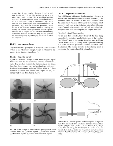
then P 5.4 kW (7.2 hp). Also, reducing n has a large Figure 10.20a and b illustrates the characteristic velocity pro-
effect on P. Such changes affect P, the blend number,
nt 5R , and R; so the problem could be explored further files for axial-flow and radial-flow impellers, respectively. The
(most conveniently) using a spreadsheet, e.g., Table maximum shear is located at the radial distance from
CD10.4. Note that in trying to achieve similarity for the the centerline of the jet at which dv=dy is maximum, which
parameter, nt 5R , adds an additional parameter, which occurs, in each case, at the inflection point of the Gaussian
reinforces the idea that multiple points of similarity are curve. Comparing the two velocity profiles, it is seen that dv=dy
simply not feasible. These parameters indicate ‘‘goals,’’ is higher for the radial-flow impeller, i.e., higher shear rate.
which warrant cognizance but are not simultaneously
achievable. As noted by Oldshue, they provide guidance 10.4.2.2.1 Axial-Flow Impellers
for a modeling study or, indeed, by evaluation of a full- For an axial-flow impeller, the velocity of the fluid being
scale system. pumped is, by definition, parallel to the axis of the impeller.
The ‘‘classic’’ one is the marine impeller, seen in Figure
10.20a, which has an increasing blade angle from blade tip
10.4.2 IMPELLERS AND TANKS to hub, and a constant pitch and a constant shear rate across
its diameter. The marine impeller is the starting point in
Impellers and tanks go together as a ‘‘system.’’ The reference
considering the variety of axial-flow impellers.
system is the ‘‘Rushton’’ design, which is referred to fre-
quently in the literature (see glossary).
10.4.2.1 Impeller Variety
Figure 10.19 shows a sample of four impeller types. Figure
10.19a and b are the two basic ones: a marine impeller and a dy
radial-flow impeller, respectively. Between these two types,
there is a large variety, e.g., perhaps hundreds, with many dv
developed as proprietary products (Oldshue, 1983, p. 2). Two
examples of others are: mixed flow, Figure 10.19c, and v
curved-blade radial flow, Figure 10.19d.
y
(a)
(a) (b)
v
dy
dv
y
(b)
FIGURE 10.20 Velocity profiles for two categories of impellers:
Axial flow and radial flow. (a) Marine impeller. (b) Radial-flow
(c) (d) impeller. (Adapted from Oldshue, J.Y. and Trussell, R.R., Design
of impellers for mixing, in: Amirtharajah, A., Clark, M.M., and
FIGURE 10.19 Sample of impeller types (photograph of model Trussell, R.R. (Eds.), Mixing in Coagulation and Flocculation,
impellers from a set). (a) Marine impeller. (b) Radial-flow impeller. American Water Works Research Foundation, Denver, CO, p. 311,
(c) Mixed-flow impeller. (d) Curved-blade radial-flow impeller. 1991.)