
Page 310 - Fundamentals of Water Treatment Unit Processes : Physical, Chemical, and Biological
P. 310
Mixing 265
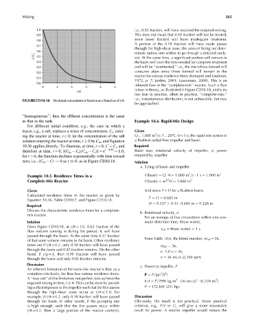
1.0 i.e., 0.82 fraction, will have received the required mixing.
0.9 This does not mean that 0.18 fraction will not be treated;
0.8 some lesser fraction will have inadequate treatment.
A portion of the 0.18 fraction will have made passes
0.7
through the high-shear zone, the amount being not deter-
0.6 minate (unless one wishes to go through a detailed analy-
C/C i 0.5 sis). At the same time, a significant portion will remain in
0.4 the basin well over the time needed for complete treatment
0.3 and will be ‘‘overtreated,’’ i.e., the microflocs formed will
0.2 consume alum since those formed will remain in the
reactor for various residence times (Stenquist and Kaufman,
0.1
1972, p. 7; Jorden, 2001; Kawamura, 2000). This is an
0.0
0 1 2 3 4 5 inherent flaw in the ‘‘complete-mix’’ reactor. Such a flaw
is true in theory, as illustrated in Figure CD10.18, and is no
t/θ
less true in practice, albeit in practice, ‘‘complete-mix,’’
i.e., instantaneous distribution, is not achievable, but may
FIGURECD10.18 Residualconcentrationfractionasafunctionoft=u.
be approached.
‘‘homogeneous’’; thus the effluent concentration is the same
as that in the tank. Example 10.6 Rapid-Mix Design
For different initial condition, e.g., the case in which a
tracer, e.g., a salt, replaces a water of concentration, C i , enter- Given
3
ing the reactor at time, t < 0; let the concentration of the salt Q ¼ 1.000 m =s; T ¼ 208C; u 1 s; the rapid-mix system is
solution entering the reactor at time, t 0be C in , and Equation a Rushton radial-flow impeller and basin.
10.36 applies directly. To illustrate, at time, t ¼ 0, C ¼ C i , and Required
therefore at time, t ¼ 0, [(C in C i )=C in C i )] ¼ e [ 0=u] ¼ 1.0; Basin size; rotational velocity of impeller, n; power
for t > 0, the function declines exponentially with time toward required by impeller
zero, i.e., (C in C) ! 0as t >> 0, as in Figure CD10.18. Solution
a. Sizing of basin and impeller
3
Example 10.5 Residence Times in a V(basin) ¼ Q u ¼ 1:000 m =s 1s ¼ 1:000 m 3
Complete-Mix Reactor V(basin) ¼ pT H ¼ 1:000 m 3
2
Given And since T ¼ H for a Rushton basin,
Calculated residence times in the reactor as given by
Equation 10.36, Table CD10.7, and Figure CD10.18. T ¼ H ¼ 0:683 m
D ¼ 0:33T ¼ 0:33 0:683 m ¼ 0:228 m
Required
Discuss the characteristic residence times for a complete- b. Rotational velocity, n
mix reactor.
For an average of five circulations within one raw-
Solution water detention time, u(raw water),
From Figure CD10.18, at t=u ¼ 1.0, 0.63 fraction of the t 5R u(raw water) ¼ 1s
flow volume coming in during the period, u, will have
passed through the basin. At the same time 0.37 fraction
From Table 10.6, the blend number, nt 5R ¼ 36,
of that same volume remains in the basin. Other residence
times are if t=u 0.2, only 0.18 fraction will have passed nt 5R ¼ 36,
through the basin and 0.82 fraction remains. On the other n 1:0s ¼ 36;
hand, if t=q 3, then 0.95 fraction will have passed
through the basin and only 0.05 fraction remains. n ¼ 36 rev=s (2,160 rpm)
Discussion c. Power to impeller, P
An inherent limitation of the back-mix reactor is that, as a
complete-mix basin, the flow has various residence times. P ¼ P=(rn D )
5
3
A ‘‘way out’’ of this limitation, not perfect, is to achieve the 3 3 5
required mixing in time, t u. This can be done by provid- 6:0 ¼ P=[998 kg=m (36 rev=s) (0:228 m) ]
ing sufficient power to the impeller such that the five passes P ¼ 172 kW (231 hp)
through the high-shear zone occur at t=u 1:0. For
example, if t=u 0.2, only 0.18 fraction will have passed Discussion
through the basin. In other words, if the pumping rate Obviously, the result is not practical. Some practical
is high enough, such that the five passes occur within criterion, e.g., P=V or G, will give a more reasonable
t=u 0.2, then a large portion of the reactor contents, result for power. A smaller impeller would reduce the