
Page 306 - Fundamentals of Water Treatment Unit Processes : Physical, Chemical, and Biological
P. 306
Mixing 261
is to be injected into the core zone of a jet mixer that
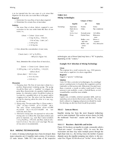
disperses the alum into raw-water flow in the pipe. TABLE 10.5
Required Mixing Technologies
1. Determine the mass flow of neat alum required. Category of Mixer
2. Determine the volume flow of neat alum.
Impeller Jet Static
Solution
1. The mass flow of alum, J(alum), required is con- Technology Open basin Nozzles Orifice
centration in the raw water times the flow of raw Draft tube in Orifice Pipe constriction
water, i.e., basin
In-line mixer Hydraulic jump Air bubbles
J(alum) ¼ C(alum) Q(raw water) Pump Parshall flume Bifurcation
¼ 10 mg Al 2 (SO 4 ) 14H 2 O=L vanes
3
3
3
3785 m =day (1000 L=m ) Baffles—over- Elbows in
and-under sequence
¼ 37,850 g=day
Baffles—end- Flow obstruction
¼ 37:85 kg=day
around
Weir
2. First, obtain the concentration of neat alum,
C(neat alum) ¼ 647 g Al 2 (SO 4 )
3
14H 2 O=L (Figure F:4): technologies; any of those listed may have a ‘‘fit’’ in practice,
depending on the ‘‘context.’’
Next, determine the volume flow of neat alum,
Example 10.4 Selection of Mixing Technology
J(alum) ¼ C(neat alum) Q(neat alum)
Given
37,850 g=day ¼ 647 g Al 2 (SO 4 ) 14H 2 O=L The engineer for a small community, e.g., 2000 persons,
3
Q(neat alum) must select a rapid mix for alum coagulation.
Q(neat alum) ¼ 58:5L=day Required
¼ 40:6mL=min Suggest a ‘‘passive’’ technology.
¼ 0:68 mL=s
Solution
Table 10.5 lists a selection of technologies. If a centrifugal
Discussion
1. Pumping alum: The flow of neat alum is done by a pump is used just prior to the plant, the coagulant could be
positive displacement metering pump. The pump metered-in on the suction side. If the plant is located lower
should be fitted with a ‘‘snubber’’ to mitigate the than a reservoir, a nozzle or orifice could work. If water
pulse flow characteristic of a positive displacement pressure is not available, a weir, a Parshall flume, or end-
pump. An alternative system should be in place to around baffles would be most reliable.
account for a possible failure of the pump and=or Discussion
clogging of the line. The alum feed line should be Capital cost, reliability, minimal operation skills, and low
set up for cleaning while the other is in use, e.g., operating cost are factors that relate to selection. The alum
by hot water. feed is subject to clogging and provision should be made
for cleaning; an alternate feed should be provided.
2. Mixing ratio: The raw-water flow is, Q(raw water) ¼
3
3
3785 m =day ¼ 0.0438 m =s ¼ 43,800 mL=s.
The ratio: Q(raw water)=Q(neat alum) ¼ 43,800
mL=s=0.68 mL=s ¼ 64,423 64,000 mL raw 10.4.1 IMPELLER MIXING
water=mL neat alum.
3. Alternative mixing ratio: An approach to reduce the Impeller mixing has been the most frequent technology
mixing ratio is to dilute the neat alum solution just used in water treatment. This section reviews theory for both
prior to injection, e.g., such that C(alum-solution) the traditional ‘‘back-mix’’ reactor and the later ‘‘in-line’’
65 g Al 2 (SO 4 ) 3 14H 2 O=L and thus, Q(alum solu- mixers.
tion) 6.4 mL=s. The ratio is still very high. The use
of neat alum is recommended.
10.4.1.1 Reactors—Back-Mix and In-Line
Figure 10.16a shows an impeller in a tank, commonly called a
‘‘back-mix reactor’’ (Levenspiel, 1972). As seen, the flow
10.4 MIXING TECHNOLOGIES
recirculates and thus may make multiple passes through the
A variety of mixing technologies have been developed; three high-shear zone (i.e., the mixing zone); the number of passes
major categories are (1) impeller–tank systems, (2) jet mixers, depends upon the impeller pumping rate relative to the raw-
(3) static mixers. Table 10.5 lists some of the respective water flow. Figure 10.16b shows an ‘‘in-line’’ mixer, which is