
Page 307 - Fundamentals of Water Treatment Unit Processes : Physical, Chemical, and Biological
P. 307
262 Fundamentals of Water Treatment Unit Processes: Physical, Chemical, and Biological
Impeller flow
Pipe flow
(a) (b)
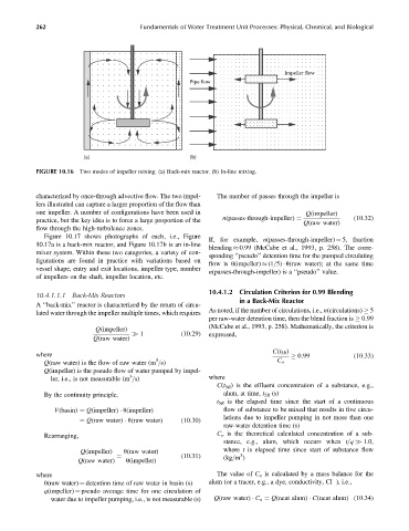
FIGURE 10.16 Two modes of impeller mixing. (a) Back-mix reactor. (b) In-line mixing.
characterized by once-through advective flow. The two impel- The number of passes through the impeller is
lers illustrated can capture a larger proportion of the flow than
one impeller. A number of configurations have been used in Q(impeller)
practice, but the key idea is to force a large proportion of the n(passes-through-impeller) ¼ (10:32)
Q(raw water)
flow through the high-turbulence zones.
Figure 10.17 shows photographs of each, i.e., Figure
If, for example, n(passes-through-impeller) ¼ 5, fraction
10.17a is a back-mix reactor, and Figure 10.17b is an in-line
blending 0.99 (McCabe et al., 1993, p. 258). The corre-
mixer system. Within these two categories, a variety of con-
sponding ‘‘pseudo’’ detention time for the pumped circulating
figurations are found in practice with variations based on
flow is u(impeller) (1=5) u(raw water); at the same time
vessel shape, entry and exit locations, impeller type, number
n(passes-through-impeller) is a ‘‘pseudo’’ value.
of impellers on the shaft, impeller location, etc.
10.4.1.2 Circulation Criterion for 0.99 Blending
10.4.1.1.1 Back-Mix Reactors
in a Back-Mix Reactor
A ‘‘back-mix’’ reactor is characterized by the return of circu-
As noted, if the number of circulations, i.e., n(circulations) 5
lated water through the impeller multiple times, which requires
per raw-water detention time, then the blend fraction is 0.99
(McCabe et al., 1993, p. 258). Mathematically, the criterion is
Q(impeller)
1 (10:29) expressed,
Q(raw water)
C(t 5R )
where 0:99 (10:33)
3
Q(raw water) is the flow of raw water (m =s) C o
Q(impeller) is the pseudo flow of water pumped by impel-
3
ler, i.e., is not measurable (m =s) where
C(t 5R ) is the effluent concentration of a substance, e.g.,
By the continuity principle, alum, at time, t 5R (s)
t 5R is the elapsed time since the start of a continuous
V(basin) ¼ Q(impeller) u(impeller) flow of substance to be mixed that results in five circu-
lations due to impeller pumping in not more than one
¼ Q(raw water) u(raw water) (10:30)
raw-water detention time (s)
Rearranging, C o is the theoretical calculated concentration of a sub-
stance, e.g., alum, which occurs when t=q >> 1.0,
Q(impeller) u(raw water) where t is elapsed time since start of substance flow
(10:31) (kg=m )
3
Q(raw water) u(impeller)
¼
where The value of C o is calculated by a mass balance for the
u(raw water) ¼ detention time of raw water in basin (s) alum (or a tracer, e.g., a dye, conductivity, Cl ), i.e.,
q(impeller) ¼ pseudo average time for one circulation of
water due to impeller pumping, i.e., is not measurable (s) Q(raw water) C o ¼ Q(neat alum) C(neat alum) (10:34)