
Page 321 - Fundamentals of Water Treatment Unit Processes : Physical, Chemical, and Biological
P. 321
276 Fundamentals of Water Treatment Unit Processes: Physical, Chemical, and Biological
To illustrate specific data for a flash mix coagulation installa- 10.4.4.2 Baffles
tion, Bob Reed, Superintendent Soldier Canyon WTP (which Another ‘‘passive’’ kind of mixing device is a system of
serves the Fort Collins, Colorado environs) provided the baffles placed in the way of the gravity flow in an open
following information (Reed, February 8, 2002). The design channel; two kinds are (1) over-and-under, and (2) end-
3
flow is 0.220 m =s (5 mgd); mixing is by a 4 in. 3.73 kW around. The first use of baffles for a large-scale water treat-
(5 hp) Water Champe with shaft entering a 1067 mm (42 in.)
ment plant was at New Orleans in 1909 (Willcomb, 1932,
raw-water pipeline from the side, i.e., the jet flow is from near p. 1431). Of some 30 plants built during the 1920s, about one-
the pipe wall directed toward the center. The unit has an third used over-and-under baffles and one-third used end-
external motor with the coagulant feed entering an induction around (Willcomb, 1932, p. 1431). Their use was common
feed tube inside the raw-water pipeline. The coagulant was until supplanted by a trend toward impeller–basin systems
also fed in front of the propeller, as an experiment, instead of beginning probably about 1940.
through the induction tube. The result was higher alum dosage
for the former feed configuration. The plant also has two jet- 10.4.4.2.1 Over-and-Under
mixer systems, each with center feed, providing redundancy An over-and-under baffle system comprises a combination of
to facilitate maintenance. weirs and sluices (most likely, for rapid mix, a single weir or
sluice unless several chemicals are added, e.g., lime, alum,
10.4.4 STATIC MIXERS polymer in succession). As with the other mixing systems,
design is based upon hydraulic principles. The water entering
The term ‘‘static mixer’’ usually means a proprietary pipe insert
the first compartment rises to a level sufficient to overflow the
consisting of a number of twisted blades, e.g., Komaxe,or
first weir plate. The coagulant is added to the overflow, and is
Kenicse, that cause a sequence of bifurcations. The static
distributed over the width by means of several orifices from a
mixer is a ‘‘passive’’ technology, i.e., there is no operator
manifold parallel to the weir crest. The water falls into the
involvement. Generically, a static mixer could mean any station-
pool, below. The depth of the pool below should be as small
ary ‘‘form’’ that induces wake turbulence (Section 10.3.1.2).
as feasible, but is determined by the opening of the sluice
(if used).
10.4.4.1 General Principles
Elbows, baffles, and other flow obstructions, create wake 10.4.4.2.2 End-Around Baffle Systems
turbulence in which headloss for a single unit is
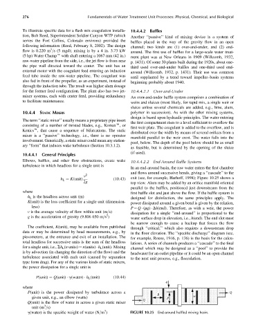
In an end-around basin, the raw water enters the first chamber
and flows around successive bends, giving a ‘‘cascade’’ to the
v 2
h L ¼ K(unit) (10:43) exit (see, for example, Harhoff, 1998); Figure 10.25 shows a
2g top view. Alum may be added by an orifice manifold oriented
parallel to the baffles, positioned just downstream from the
where first baffle slot and just above the flow. If the baffle system is
h L is the headloss across unit (m) designed for disinfection, the same principles apply. The
K(unit) is the loss coefficient for a single unit (dimension- power dissipated around a given bend is given by the relation,
less) P ¼ Q (rg) Dh(end). Therefore, as with a weir, the power
v is the average velocity of flow within unit (m=s) dissipation for a single ‘‘end-around’’ is proportional to the
2
g is the acceleration of gravity (9.806 650 m=s ) water surface drop in elevation, i.e., h(end). The end slot must
be narrow enough to cause a backup that forces the flow
The coefficient, K(unit), may be available from published through ‘‘critical,’’ which also requires a downstream drop
data or may be determined by head measurements, e.g., by in the floor elevation. The ‘‘specific discharge’’ diagram (see,
piezometers, at the entrance and exit of an installation. The for example, Rouse, 1946, p. 136) is the basis for the calcu-
total headloss for successive units is the sum of the headloss lations. A series of channels produces a ‘‘cascade’’ to the final
for a single unit, i.e., Sh L (n units) ¼ n(units) h L (unit). Mixing channel which may be designed as a ‘‘pool’’ to provide the
is by advection (in changing the direction of the flow) and the headwater for an outlet pipeline or it could be an open channel
turbulence associated with each unit (caused by separation to the next unit process, e.g., flocculation.
type form drag). For any of the various kinds of static mixers,
the power dissipation for a single unit is
P(unit) ¼ Q(unit) g(water) h L (unit) (10:44)
q
where
P(unit) is the power dissipated by turbulence across a Q
B
given unit, e.g., an elbow (watts) p w
Q
Q(unit) is the flow of water in across a given static mixer
3
unit (m =s)
3
g(water) is the specific weight of water (N=m ) FIGURE 10.25 End-around baffled mixing basin.