
Page 320 - Fundamentals of Water Treatment Unit Processes : Physical, Chemical, and Biological
P. 320
Mixing 275
0.6
v (jet at r= 0) = 0.33 m/s Water Champ ®
o
system
0.5
Flow
v (jet at r= 0) = 0.11 m/s
o
0.4
r (m) 0.3 SS guide rail system
(a)
0.2
0.1
0.0 (b)
0 1 2
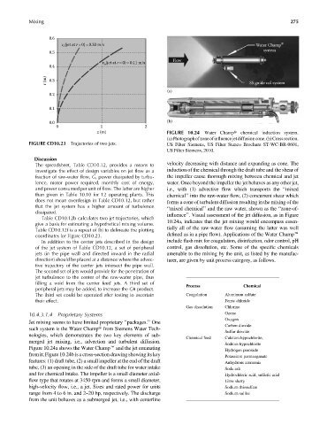
z (m) FIGURE 10.24 Water Champt chemical induction system.
(a)Photographofzoneofinfluencejetdiffusioncone.(b)Crosssection.
FIGURE CD10.23 Trajectories of two jets. US Filter Siemens, US Filter Stanco Brochure ST-WC-BR-0601,
US Filter Siemens, 2010.
Discussion
The spreadsheet, Table CD10.12, provides a means to velocity decreasing with distance and expanding as cone. The
investigate the effect of design variables on jet flow as a induction of the chemical through the draft tube and the shear of
fraction of raw-water flow, G, power dissipated by turbu- the impeller cause thorough mixing between chemical and jet
lence, motor power required, monthly cost of energy, water. Once beyond the impeller the jet behaves as any other jet,
and power consumed per unit of flow. The latter are higher i.e., with (1) advective flow which transports the ‘‘mixed
than given in Table 10.10 for 12 operating plants. This chemical’’ into the raw-water flow, (2) concurrent shear which
does not mean overdesign in Table CD10.12, but rather forms a cone of turbulent diffusion resulting in the mixing of the
that the jet system has a higher amount of turbulence ‘‘mixed chemical’’ and the raw water, shown as the ‘‘zone-of-
dissipated. influence’’. Visual assessment of the jet diffusion, as in Figure
Table CD10.12b calculates two jet trajectories, which
give a basis for estimating a hypothetical mixing volume. 10.24a, indicates that the jet mixing would encompass essen-
Table CD10.12f is a repeat of (b) to delineate the plotting tially all of the raw-water flow (assuming the latter was well
coordinates for Figure CD10.23. defined as in a pipe flow). Applications of the Water Champe
In addition to the center jets described in the design include flash mix for coagulation, disinfection, odor control, pH
of the jet system of Table CD10.12, a set of peripheral control, gas dissolution, etc. Some of the specificchemicals
jets (in the pipe wall and directed inward in the radial amenable to the mixing by the unit, as listed by the manufac-
direction) should be placed at a distance where the advec- turer, are given by unit process category, as follows.
tive trajectory of the center jets intersect the pipe wall.
The second set of jets would provide for the penetration of
jet turbulence to the center of the raw-water pipe, thus
filling a void from the center feed jets. A third set of Process Chemical
peripheral jets may be added, to increase the Gu product.
The third set could be operated after testing to ascertain Coagulation Aluminum sulfate
their effect. Ferric chloride
Gas dissolution Chlorine
10.4.3.1.4 Proprietary Systems Ozone
Oxygen
Jet mixing seems to have limited proprietary ‘‘packages.’’ One
Carbon dioxide
such system is the Water Champt from Siemens Water Tech-
Sulfur dioxide
nologies, which demonstrates the two key elements of sub-
Chemical feed Calcium hypochlorite,
merged jet mixing, i.e., advection and turbulent diffusion.
Sodium hypochlorite
Figure 10.24a shows the Water Champe and the jet emanating
Hydrogen peroxide
from it; Figure 10.24b is a cross-section drawing showing its key Potassium permanganate
features: (1) draft tube, (2) a small impeller at the end of the draft Anhydrous ammonia
tube, (3) an opening in the side of the draft tube for water intake Soda ash
and for chemical intake. The impeller is a small diameter axial- Hydrochloric acid, sulfuric acid
flow type that rotates at 3450 rpm and forms a small diameter, Lime slurry
high-velocity flow, i.e., a jet. Sizes and rated power for units Sodium thiosulfate
range from 4 to 6 in. and 2–20 hp, respectively. The discharge Sodium sulfite
from the unit behaves as a submerged jet, i.e., with centerline