
Page 351 - Fundamentals of Water Treatment Unit Processes : Physical, Chemical, and Biological
P. 351
306 Fundamentals of Water Treatment Unit Processes: Physical, Chemical, and Biological
Bacteria
++ ++ ++ Polysaccharide
++
Lectin-like protein
+
+
Divalent cation
FIGURE 11.10 Depiction of role of lectins, along with polysac-
charides and divalent metals, in aggregation of bacteria. (Adapted
from Higgens, M.J. and Novak, J.T., J. Environ. Eng. Division,
ASCE, 123(EED5), 484, 1997.)
BOX 11.2 POLYMERS
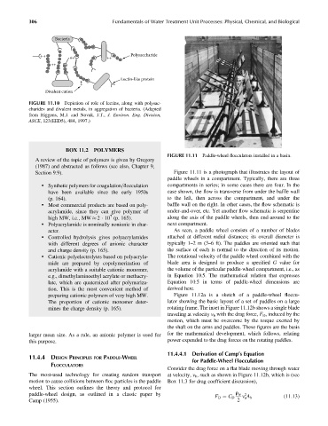
FIGURE 11.11 Paddle-wheel flocculators installed in a basin.
A review of the topic of polymers is given by Gregory
(1987) and abstracted as follows (see also, Chapter 9,
Section 9.9). Figure 11.11 is a photograph that illustrates the layout of
paddle wheels in a compartment. Typically, there are three
. Synthetic polymers for coagulation=flocculation compartments in series; in some cases there are four. In the
have been available since the early 1950s case shown, the flow is transverse from under the baffle wall
(p. 164). to the left, then across the compartment, and under the
. Most commercial products are based on poly- baffle wall on the right. In other cases, the flow schematic is
acrylamide, since they can give polymer of under-and-over, etc. Yet another flow schematic is serpentine
7
high MW, i.e., MW 2 10 (p. 165). along the axis of the paddle wheels, then end-around to the
. Polyacrylamide is nominally nonionic in char- next compartment.
acter. As seen, a paddle wheel consists of a number of blades
. Controlled hydrolysis gives polyacrylamides attached at different radial distances; its overall diameter is
with different degrees of anionic character typically 1–2m(3–6 ft). The paddles are oriented such that
and charge density (p. 165). the surface of each is normal to the direction of its motion.
. Cationic polyelectrolytes based on polyacryla- The rotational velocity of the paddle wheel combined with the
mide are prepared by copolymerization of bladearea is designed to produceaspecified G value for
acrylamide with a suitable cationic monomer, the volume of the particular paddle-wheel compartment, i.e., as
e.g., dimethylaminoethyl acrylate or methacry- in Equation 10.5. The mathematical relation that expresses
late, which are quaternized after polymeriza- Equation 10.5 in terms of paddle-wheel dimensions are
tion. This is the most convenient method of derived here.
preparing cationic polymers of very high MW. Figure 11.12a is a sketch of a paddle-wheel floccu-
The proportion of cationic monomer deter- lator showing the basic layout of a set of paddles on a large
mines the charge density (p. 165). rotating frame. The inset in Figure 11.12b shows a single blade
traveling at velocity v b with the drag force, F D , induced by the
motion, which must be overcome by the torque exerted by
the shaft on the arms and paddles. These figures are the basis
larger mean size. As a rule, an anionic polymer is used for for the mathematical development, which follows, relating
this purpose. power expended to the drag forces on the rotating paddles.
11.4.4.1 Derivation of Camp’s Equation
11.4.4 DESIGN PRINCIPLES FOR PADDLE-WHEEL
for Paddle-Wheel Flocculation
FLOCCULATORS
Consider the drag force on a flat blade moving through water
The most-used technology for creating random transport at velocity, v b , such as shown in Figure 11.12b, which is (see
motion to cause collisions between floc particles is the paddle Box 11.3 for drag coefficient discussion),
wheel. This section outlines the theory and protocol for
paddle-wheel design, as outlined in a classic paper by r w 2
F D ¼ C D v A b (11:13)
b
Camp (1955). 2