
Page 347 - Fundamentals of Water Treatment Unit Processes : Physical, Chemical, and Biological
P. 347
302 Fundamentals of Water Treatment Unit Processes: Physical, Chemical, and Biological
p
z is the packing factor, indicating how the monomers are For the Euclidian model, D F ¼ 3 and z ¼ p=(3 2) ¼ 0:7405;
packed (dimensionless) the latter applies for close-cluster packing. The value of
D F is the parameter that characterizes the fractal dimension z depends also on the shapes of the monomers, i.e., if other
of aggregates with respect to its three-dimensional than spherical, which is likely. The usual assumption for the
geometry; see Box 11.1 (dimensionless) traditional model, however, as depicted in Figure 11.6a, is that
z ¼ 1, which means that there is no pore space due to packing
effects (which, of course, cannot be true). The diameter, d,of
the fractal aggregate is a pseudo dimension, since a fractal, by
definition, is difficult to characterize. Dimensions that could
BOX 11.1 FRACTAL DIMENSION, D F
serve include (1) the ‘‘hydraulic’’ diameter (based upon the fall
The fractal dimension, D F , seen as the exponent in velocity with diameter calculated by Stoke’s law) and (2) the
Equation 11.9 has become a common parameter diameter calculated from the radius of gyration (Lee et al.,
among those who wish to pursue the idea of floc geom- 2000, p. 1990; Chakraborti et al., 2000, p. 3969). For fractals,
etry in terms of fractal theory, as developed largely since i.e., D F < 3, the lower values represent large, highly branched,
the about the mid-1980s. Gregory (1989, p. 215) and loosely bound structures (Chakraborti et al., 2000,
explained this parameter as follows: A solid p. 3969). For reference, values given for coagulation of min-
three-dimensional body has a mass, which depends on erals with 4.5 mg=L alum and 1 mg=L polymer (Purifloc A-23,
the third power of some characteristic length (such as the Dow Chemical) were D F (illite) 1.49, D F (montmorillonite)
diameter of a sphere), so that a log–log plot of mass 1.79, D F (calcite) 1.65, and D F (silt) 1.37.
against size should give a straight line with a slope of Table 11.3 gives D F values with descriptions of suspensions
three. When such plots are made for aggregates, how- for lake water and a montmorillonite suspension after alum
ever, lower slopes are found, with non-integer values. coagulation by charge neutralization, and ‘‘sweep floc,’’ respect-
The slope of the line is known as the fractal dimension, ively (Chakraborti et al., 2000, p. 3969). The initial suspension
D F . In three-dimensional space, D F may take values was without coagulant. The charge neutralization stage was
between 1 and 3, the lower value representing a linear defined by the coagulant dosage required to give a floc zeta
aggregate and the upper one an aggregate of uniform potential for a minimum settled water turbidity before restabili-
density or porosity. Generally intermediate values are zation (and higher turbidity). For lake water, this was for zeta
found, and the lower the fractal dimension, the more potential 1 mV and for the montmorillonite suspension, zeta
‘‘open’’ or ‘‘stringy’’ the aggregate structure. The earli- potential 15 mV (with alum dosages 3 and 2 mg=L, respec-
est attempts at computer simulation of aggregation were tively). The sweep-floc stage was defined as the minimum alum
based on the random addition of single particles to dose that resulted in a settled water turbidity 1ntu(14mg=L
growing clusters, which gives D F ¼ 2.75, indicating a for lake water and 20 mg=L for the montmorillonite suspension).
fairly compact aggregate structure. An alternative model As seen in Table 11.3, the fractal dimension parameter decreases
is for cluster–cluster aggregation which is more like real with increasing fractal size, indicating a looser, more spread-out
flocculation which leads to a much lower value of D F , structure as corroborated by in situ photographs. Also, as
i.e., D F ¼ 1.75, indicating a fairly ‘‘open’’ structure. described, the larger aggregates are more irregular in structure,
with the primary particles for the sweep floc being surrounded
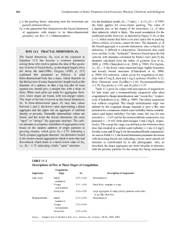
TABLE 11.3
Descriptions of Floc at Three Stages of Coagulation
Coagulation
Suspension Stage D F Description of Suspension
Lake water Initial 2.93 0.20 Heterodisperse
suspension
Charge 2.57 0.20 Small flocs, irregular in shape
neutralization
Sweep floc 2.12 0.50 Large aggregates of many primary particles surrounded
by gel-like alum floc
Montmorillonite Initial 2.71 0.20 Heterodisperse
suspension
Charge 2.51 0.20
neutralization
Sweep floc 2.39 0.30
Source: Adapted from Chakraborti, R.K. et al., Environ. Sci. Technol., 34(18), 3969, 2000.