
Page 571 - Fundamentals of Water Treatment Unit Processes : Physical, Chemical, and Biological
P. 571
526 Fundamentals of Water Treatment Unit Processes: Physical, Chemical, and Biological
2
2
HLR (gpm/ft ) HLR (gpm/ft )
0 5 10 5 C 10 15 8 7 100 0 1 2 3 5 C 10 5 15 20 6
15
4
20
Pressure loss (kPa/m bed depth) 60 35 C 25 6 5 4 3 Pressure loss (psi/ft bed depth) Bed expansion (%) 60 35 C
20
50
80
25
40
30
30
30
40
20
10
0 2 1 0 20
0
0 10 20 30 40 50 0 5 10 15
(a) HLR (m/h) (b) HLR (m/h)
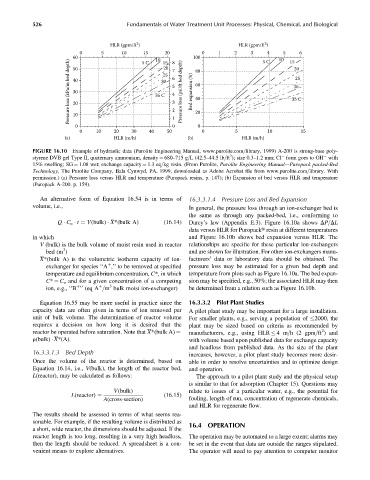
FIGURE 16.10 Example of hydraulic data (Purolite Engineering Manual, www.purolite.com=library, 1999) A-200 is strong-base poly-
3
styrene DVB gel Type II, quaternary ammonium, density ¼ 680–715 g=L (42.5–44.5 lb=ft ); size 0.3–1.2 mm; Cl form goes to OH with
15% swelling; SG ¼ 1.08 wet; exchange capacity ¼ 1.3 eq=kg resin. (From Purolite, Purolite Engineering Manual—Puropack packed-Bed
Technology, The Purolite Company, Bala Cynwyd, PA, 1999, downloaded as Adobe Acrobat file from www.purolite.com=library. With
permission.) (a) Pressure loss versus HLR and temperature (Puropack resins, p. 147); (b) Expansion of bed versus HLR and temperature
(Puropack A-200. p. 159).
An alternative form of Equation 16.54 is in terms of 16.3.3.1.4 Pressure Loss and Bed Expansion
volume, i.e., In general, the pressure loss through an ion-exchanger bed is
the same as through any packed-bed, i.e., conforming to
Q C o t ¼ V(bulk) X*(bulk A) (16:14) Darcy’s law (Appendix E.3). Figure 16.10a shows DP=DL
data versus HLR for Puropackt resin at different temperatures
in which and Figure 16.10b shows bed expansion versus HLR. The
V (bulk) is the bulk volume of moist resin used in reactor relationships are specific for these particular ion-exchangers
3
bed (m ) and are shown for illustration. For other ion-exchangers manu-
X*(bulk A) is the volumetric isotherm capacity of ion- facturers’ data or laboratory data should be obtained. The
exchanger for species ‘‘A ,’’ to be removed at specified pressure loss may be estimated for a given bed depth and
þ
temperature and equilibrium concentration, C*, in which temperature from plots such as Figure 16.10a. The bed expan-
C* ¼ C o and for a given concentration of a competing sion may be specified, e.g., 50%; the associated HLR may then
3
ion, e.g., ‘‘B ’’ (eq A =m bulk moist ion-exchanger) be determined from a relation such as Figure 16.10b.
þ
þ
Equation 16.55 may be more useful in practice since the 16.3.3.2 Pilot Plant Studies
capacity data are often given in terms of ion removed per A pilot plant study may be important for a large installation.
unit of bulk volume. The determination of reactor volume For smaller plants, e.g., serving a population of 2000, the
requires a decision on how long it is desired that the plant may be sized based on criteria as recommended by
2
manufacturers, e.g., using HLR 4m=h (2 gpm=ft ) and
reactor be operated before saturation. Note that X*(bulk A) ¼
r(bulk) X*(A). with volume based upon published data for exchange capacity
and headloss from published data. As the size of the plant
16.3.3.1.3 Bed Depth
increases, however, a pilot plant study becomes more desir-
Once the volume of the reactor is determined, based on able in order to resolve uncertainties and to optimize design
Equation 16.14, i.e., V(bulk), the length of the reactor bed, and operation.
L(reactor), may be calculated as follows: The approach to a pilot plant study and the physical setup
is similar to that for adsorption (Chapter 15). Questions may
V(bulk) relate to issues of a particular water, e.g., the potential for
(16:15)
A(cross-section) fouling, length of run, concentration of regenerate chemicals,
L(reactor) ¼
and HLR for regenerate flow.
The results should be assessed in terms of what seems rea-
sonable. For example, if the resulting volume is distributed as 16.4 OPERATION
a short, wide reactor, the dimensions should be adjusted. If the
reactor length is too long, resulting in a very high headloss, The operation may be automated to a large extent; alarms may
then the length should be reduced. A spreadsheet is a con- be set in the event that data are outside the ranges stipulated.
venient means to explore alternatives. The operator will need to pay attention to computer monitor