
Page 570 - Fundamentals of Water Treatment Unit Processes : Physical, Chemical, and Biological
P. 570
Ion-Exchange 525
16.3.3 REACTOR DESIGN
The reactor is the heart of the ion-exchange system. As noted
A B C
in Section 16.2, the theory is similar to any packed-bed, e.g.,
Partially Fresh Recharging adsorption or filtration (see also Section 4.2.2.6).
exhausted bed bed The reactor design requires knowledge of ion-exchange
bed capacity and an understanding of kinetics as related to wave
fronts (Section 15.2.3), e.g., the steeper the wave front the
faster the rate of uptake. Practically, the design requires deter-
mination of the hydraulic loading rate, and sizing of the reactor
(a) volume (Section 15.2.4). Both are described in the following.
16.3.3.1 Summary of Design Data
A hydraulic loading rate (HLR) criterion is the basis for
A B C
determining the cross-sectional area. The reactor volume is
based on the duration of run desired and the capacity of the
Recharging Partially Fresh
bed exhausted bed ion-exchanger (in terms of the isotherm for the influent
bed concentration of the target ion to be removed). The bed
depth results from these calculations. Pressure loss is another
design issue, and depends upon both the media and its depth.
(b) 16.3.3.1.1 Hydraulic Loading Rate
Examples of recommended HLR values (Rohm and Haas,
1987, pp. 27, 33) are HLR (operation) 2.5–5.0 m=h (1.0–
2
A B C 2.0 gpm=ft ). The hydraulic loading rate selected yields the
total cross-sectional area for all columns in aggregate, i.e.,
Fresh Recharging Partially
bed bed exhausted Q (16:12)
A ¼
bed HLR
which ‘‘sizes’’ this part of the column. After determining the
(c) volume, the length of the packed-bed may be calculated, i.e.,
L(packed-bed) A(cross section) ¼ V(packed-bed).
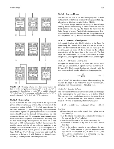
FIGURE 16.9 Operating scheme for a three-reactor system. (a)
Start of cycle: ‘‘A’’ partially exhausted, ‘‘B’’ is fresh bed, ‘‘C’’ is 16.3.3.1.2 Reactor Volume
recharging. (b) Second phase of cycle: ‘‘B’’ is partially exhausted, The calculation of the mass (or volume) of an ion-exchanger
‘‘C’’ is fresh bed, ‘‘A’’ is recharging. (c) Third phase of cycle: ‘‘C’’ is is the same as given for adsorption, i.e., as in Section 15.2.4.
partially exhausted, ‘‘A’’ is fresh bed, ‘‘B’’ is recharging.
The corresponding mass balance equation (the mass flow of
an ion, ‘‘A’’ into the reactor for a time duration, t, equals the
16.3.2.3 Regeneration
mass of ‘‘A’’ that is retained by the ion-exchanger) is
Figure 16.8 shows the basic components of the regeneration
portion of the ion-exchange system. The components of the Q C o t ¼ M(dry ion exchanger) X*(A) (16:13)
regeneration system include: (1) finished water storage for
backwash and rinse, (2) pumps and piping for backwash and in which
rinse, (3) holding tank for spent regenerate and backwash and Q is the flow of water to be treated, into a given reactor
3
rinse water, (4) sewer for disposal, (5) tank or tanks for bulk column (m =s)
regenerate storage, and (6) regenerate measurement tanks. C o is the influent concentration of ions reactor column, to
3
These units also have pumps and associated plumbing. The be removed (kg A =m solution)
þ
finished water storage should provide for about 10–15 min t is the desired duration of run before exhausting (s)
backwash at 50% bed expansion; the HLR depends upon the M (dry resin) is the mass of dry resin to be used in reactor
specific gravity and size of ion-exchanger material; as an bed (kg)
example, for Amberlite IR-120 resin, 50% bed expansion is X*(A) is the isotherm capacity of ion-exchanger for spe-
2
achieved at HLR 15 m=h (6 gpm=ft )at 228C (Rohm and cies ‘‘A ,’’ to be removed at specified temperature and
þ
Haas, 1987, p. 27). Following regeneration additional the equilibrium concentration, C*, in which C* ¼ C o and
regenerate is drained and with flushing by finished water. for a given concentration of a competing ion, e.g.,
The design should provide for drainage and rinse. ‘‘B ’’ (eq A =kg dry ion-exchanger)
þ
þ