
Page 569 - Fundamentals of Water Treatment Unit Processes : Physical, Chemical, and Biological
P. 569
524 Fundamentals of Water Treatment Unit Processes: Physical, Chemical, and Biological
TABLE 16.4
Examples of Ion-Exchanger Groups and Associated Properties
Capacity d
d 10 Size r Moisture
Name Group Cat c DVB (%) meq=g meq=mL (mm) UC (Mesh) (g=L) P (%)
Polystyrene –SO 3 SA 8 5.35 0
Amberlite IR-120 a –SO 3 a SA 8 5.0 1.9 wet 0.50 1.6 16–50 816 0.40 44–48
Dowex 50W b SA 8 5.0 1.7 wet 20–50 787 0.40 53
Amberlite IRA-400 –N(alkyl) 3 þ SB 8 2.6 1.2 42–48
b
Dowex Marathon A Quaternary amine SB Gel 2.4 0.58 1.1 670 50–60
Amberlite IR-45 a Amino groups WB 5 2 37–45
a e
Amberlite IRA 743 Methylglucamine 4–7mgB 0.7 1.6 700
Clinoptilolite 0.15 f
Glauconite 0.23 g
Activated alumina 0.0046 mg F-
Notes: Density is g moist resin=L packed-bed. Moisture is percent on dry weight basis. All resins listed are polystyrene matrix. All resins listed are in bead
form.
a
Rohm and Haas (1987, p. 27) Philadelphia, PA.
b Dow Chemical, Midland, MI (1964, p. 74); Marathon A from www.dow.com=liquidseps=pc=jump=dowex=
c
Categories are: SA, strong acid; WA, weak acid; SB, strong base; WB, weak base.
d
Capacity: (1) meq=g dry resin; (2) meq=mL packed-bed.
e
Boron selective; capacity is as mg B=mL packed-bed.
f
Marshall (1964, p. 120).
g
Babbitt and Doland (1949, p. 513).
(an example of a weak-acid type is missing), chelating, zeo-
lite, and activated alumina. Available data are given for two Raw water
zeolites and activated alumina. The purpose of the table is to
provide an idea of the variety of ion-exchangers and values of
Pretreatment
characteristic parameters.
P
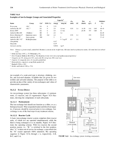
16.3.2 SYSTEM DESIGN
An ion-exchange system has three subsystems: (1) pretreat- x
ment, (2) reaction, and (3) regeneration. Figure 16.8 illus- P
trates, showing the components of each subsystem.
Regenerant
measurement
16.3.2.1 Pretreatment Ion tank
The ion-exchange bed should not function as a filter, or as a exchange
reactor
biological reactor. Thus suspended matter and dissolved organ-
ics, if present, should be removed prior to ion-exchange. Ion- Backwash and rinse disposal Regenerant
bulk
exchange is one of the final steps in any treatment scheme. storage
Backwash and rinse
16.3.2.2 Reactor Cycle
A basic ion-exchange reactor system comprises three reactor x
units, of which two are operated simultaneously while the Spent
third is being recharged or is on standby. Figure 16.9 illus- Finished regenerant
trates the operating scheme. With two reactors the second water storage holding tank
position reactor, i.e., ‘‘B,’’ is switched to the first position,
Disposal
after ‘‘A’’ is taken out of service for recharge, a step which lets
the ‘‘B’’ reactor approach 100% saturation. The operating USE Sewer
sequence in Figure 16.9a through c is, respectively, A-B,
B-C, and C-A. FIGURE 16.8 Ion-exchange system showing components.