
Page 585 - Fundamentals of Water Treatment Unit Processes : Physical, Chemical, and Biological
P. 585
540 Fundamentals of Water Treatment Unit Processes: Physical, Chemical, and Biological
BOX 17.1 MEMBRANE BOX 17.2 MICRO=ULTRA AND NANO=RO
KNOWLEDGE BASE
Another organizing dilemma is whether to consider the
Membrane technology is underpinned by a network of two categories of membranes as separate or to integrate
scientists, engineers, consulting firms, equipment manu- them. They are integrated for the purposes of this chap-
facturer’s, manufacturer’s representatives, academics, ter. Categories also could be based on source water,
operators, industries, and municipalities using the tech- application, membrane material, shape of membrane
nology, etc. The topic is discussed at meetings, sem- element (e.g., spiral-wound, hollow tube, and hollow
inars, journals, Web sites, etc., which result in the fiber), configuration of a membrane assembly, driving
exchange of ideas and advancement and dissemination force, etc.
of knowledge. The larger parent areas of knowledge
include environmental engineering, mechanical engin-
eering, polymer science, the water treatment industry,
etc. The foregoing description is not, of course, unique
to membranes; other water treatment unit processes Pressure vessel
have their own respective knowledge bases.
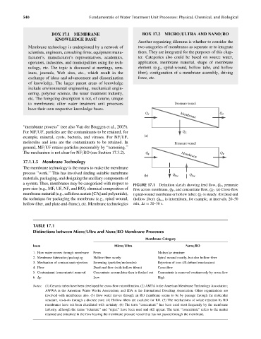
Q F Membrane Q P
‘‘membrane process’’ (see also Van der Bruggen et al., 2003).
For MF=UF, particles are the contaminants to be retained, for Q C
example, mineral, cysts, bacteria, and viruses. For NF=UF, (a)
molecules and ions are the contaminants to be retained. In Pressure vessel
general, MF=UF retains particles presumably by ‘‘screening.’’
The mechanism is not clear for NF=RO (see Section 17.3.2). Q F Membrane Q P
17.1.1.5 Membrane Technology
The membrane technology is the means to make the membrane
process ‘‘work.’’ This has involved finding suitable membrane
(b) Q bw Q bw
materials, packaging, and designing the ancillary components of
a system. Thus, membranes may be categorized with respect to FIGURE 17.1 Definition sketch showing feed flow, Q F , permeate
pore size (e.g., MF, UF, NF, and RO), chemical composition of flow across membrane, Q P , and concentrate flow, Q C . (a) Cross-flow
membrane material (e.g., cellulose acetate [CA] and polyamide), (spiral-wound membrane or hollow tube): Q C is steady. (b) Dead end
the technique for packaging the membrane (e.g., spiral wound, (hollow fiber): Q bw , is intermittent, for example, at intervals, 20–50
hollow fiber, and plate-and-frame), etc. Membrane technologies min, Dt 20–30 s.
TABLE 17.1
Distinctions between Micro=Ultra and Nano=RO Membrane Processes
Membrane Category
Issue Micro=Ultra Nano=RO
1. How water moves through membrane Pores Molecular structure
2. Membrane fabrication=packaging Hollow fiber mostly Spiral wound mostly, but also hollow fiber
3. Mechanism of contaminant rejection Screening (particles=molecules) Rejection of ions (ill-defined mechanism)
4. Flow Dead-end flow (with hollow fibers) Cross-flow
5. Contaminant (concentrate) removal Concentrate accumulates then is flushed out Concentrate is removed continuously by cross-flow
6. Dp Low High
Notes: (1) Ceramic tubes have been developed for cross-flow microfiltration. (2) AMTA is the American Membrane Technology Association;
AWWA is the American Water Works Association; and IDA is the International Desalting Association. Other organizations are
involved with membranes also. (3) How water moves through an RO membrane seems to be by passage through the molecular
structure, vis-à-vis through a discrete pore. (4) Hollow fibers are available for RO. (5) The mechanisms of solute rejection by RO
membranes have not been elucidated with certainty. (6) The term ‘‘concentrate’’ has been used most frequently by the membrane
industry, although the terms ‘‘retentate’’ and ‘‘reject’’ have been used and still appear. The term ‘‘concentrate’’ refers to the matter
retained and entrained in the flow leaving the membrane pressure vessel that has not passed through the membrane.