
Page 590 - Fundamentals of Water Treatment Unit Processes : Physical, Chemical, and Biological
P. 590
Membrane Processes 545
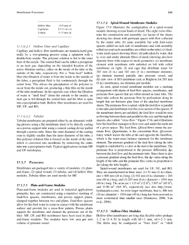
17.1.7.2 Spiral-Wound Membrane Modules
Hollow fiber 0.9 mm od
Figure 17.8 illustrates the configuration of a spiral-wound
Capillaries 0.5–5mm od
module showing several kinds of detail. The eight views illus-
Tubular 5–15 mm od
trate the construction and assembly: (a) layout of the sheets
showing two sheets with permeate spacer with flow collected
by the center tube; (b) same assembly but with feed-water
17.1.6.2.1 Hollow Fiber and Capillary spacers added on each side of membranes and with assembly
rolled (several such assemblies are rolled on the tube); (c) feed-
Capillary and hollow fiber membranes are manufactured gen-
water mesh spacer showing fibers; (d) path taken by water, that
erally by a wet-spinning process using a spinneret with a
is, over-and-under alternate fibers of mesh (showing also how
double-bore nozzle. The polymer solution is fed to the outer
deposits form with respect to mesh geometry); (e) membrane
bore of the nozzle. The central fluid can be either a precipitant
element with membrane rolls unfurled on left with rolled
or an inert gas, depending on the intended location of the
membrane on right; (f) end caps that distribute water for
active filtration surface, either on the inside of the tube or the
203 mm (8 in.) and 102 mm (4 in.) membrane elements;
outside of the tube, respectively. For a ‘‘bore-feed’’ hollow
(g) element inserted partially into pressure vessel; and
fiber (the filtration of water is from the inside to the outside of
(h) side view of RO membrane rack at Brighton for 203 mm
the tube), a precipitant fluid is fed continuously through the
(8 in.) membranes, six elements per module.
center bore. This allows the precipitation of the polymer to
As seen, spiral-wound membrane modules use a stacking
occur from the inside out, producing a thin film on the inside
arrangement with sheets of feed-flow spacers, membranes, and
of the tube membrane. In the opposite case where the filtration
permeate-flow spacers that are rolled around an inner tube. The
of water is ‘‘shell feed’’ (from the outside to the inside), an
inner tube collects the permeate flow by perforations along its
inert gas is fed through the central bore and the fiber is spun
length that are between glue lines of the attached membrane
into a precipitation bath. Hollow-fiber membranes are used for
sheets. The permeate flow is spiral, while the feed flow is parallel
MF, UF, and RO.
to the tube and distributed over the cross section of the spacers. If
the membrane sheets are unfolded, the feed flow would be seen
17.1.6.2.2 Tubular as flowing between them and parallel to the axis and through the
Tubular membranes are prepared either by an ultrasonic weld- spacers, also called, ‘‘cross-flow.’’ Figure 17.8c and d illustrates
ing process using a flat membrane sheet or by directly casting how the feed flow manages to flow over-and-under the mesh-net
on a porous support tube using a conical casting device pulled of a given spacer. The feed-flow, Q(feed-flow) minus the per-
through a porous tube. Since the outer diameter of the casting meate flow, Q(permeate), is the concentrate flow, Q(concen-
cone is slightly smaller than the inner diameter of the tube, a trate), which leaves the tube at the end opposite the feed-flow,
thin polymer solution film is formed on the inside of the tube, which is the water-mass balance statement for the membrane
which is converted into membrane by immersing the entire element. The pressure gradient of the feed flow (along the tube
tube into a precipitation bath. Typical applications include MF length) is controlled by a valve at the end of the membrane. The
and UF membranes. permeate flux is proportional to the pressure differential, Dp,
between the feed flow and the permeate tube. Since there is also
a pressure gradient along the feed flow, the Dp varies along the
length of the tube and the permeate flux varies in proportion to
17.1.7 PACKAGING
Dp (along the tube length).
Membranes are packaged into a variety of modules: (1) plate- Spiral-wound membranes are used for UF, NF, and RO.
and-frame, (2) spiral wound, (3) tubular, and (4) hollow fiber They are manufactured in three sizes: (1) 51 mm (2 in.) diam-
modules. Tubular filters are used mostly for MF. eter 600 mm (24 in.) long, (2) 102 mm (4 in.) diameter 203
mm (40 in.) long, and (3) 203 mm (8 in.) diameter 1016 mm
2
2
2
2
(40 in.) long. The areas are 1.115 m (12 ft ), 7.897 m (85 ft ),
17.1.7.1 Plate-and-Frame Modules 2 2
and 33.90 m (365 ft ), respectively (see also http:==www.
Plate-and-frame modules are used in industrial applications
hydranautics.com). An even larger membrane, that is, 406 mm
primarily; they are constructed using a repetitive stacking of
(16 in.) diameter 1016 mm (40 in.) long has been assessed as
feed-flow spacers, membranes, and porous support plates,
more economical than smaller sizes (Furukawa, 2006; Yun
clamped together between two end plates. Feed-flow spacers
et al., 2006).
allow for the feed water to come in contact with the membrane
surface and provide for a cross-flow pattern. Porous plates
support the membrane and channel the permeate out of the 17.1.7.3 Hollow-Fiber Modules
filter. MF, UF, and RO membranes have been used in plate- Hollow-fiber membranes are long thin flexible tubes perhaps
and-frame modules. The modules have low area per unit 1–2m(3–6 ft) in length with id 1mm,od 2–3mm.
volume of pressure vessel. The fibers may be configured as ‘‘bore feed’’ or ‘‘shell