
Page 591 - Fundamentals of Water Treatment Unit Processes : Physical, Chemical, and Biological
P. 591
546 Fundamentals of Water Treatment Unit Processes: Physical, Chemical, and Biological
Perforated
tube
Leaf
thickness Glued to Leaf width
perforated tube
Perforated
tube
Glued
edges
Membrane Feed water spacer
Permeate water spacer Leaf length Membrane
Membrane Permeate water spacer
Membrane
Feed water spacer
(a) (b)
Plastic Upper fiber
fibers
NOM deposits
elongated in the
direction of flow
Flow path
Top fiber Lower fiber through spacer
layer 1 mm 200kV 2.42E1 0006/22 NO5 p503
NOM deposits
Bottom fiber Feed water Clean
layer flow path surface
Feed water
spacer outline
1 mm 19.9 kV 2.32E1 0012/22 H25P109
(c) (d)
Unwound element
Wound element
8 in. diameter
5
4 1 4 in. diameter
3 2
Five membrane leafs
(e) (f)
End caps with connected
Pressure vessel
feed water plumbing
housings
Experimental membrane
element being inserted
(g) (h)
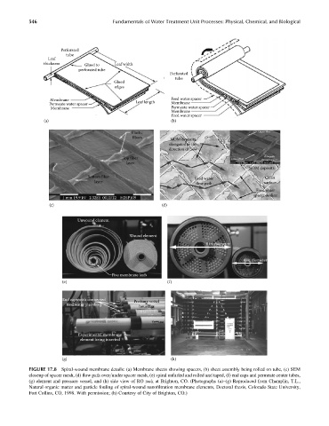
FIGURE 17.8 Spiral-wound membrane details: (a) Membrane sheets showing spacers, (b) sheet assembly being rolled on tube, (c) SEM
closeup of spacer mesh, (d) flow path over=under spacer mesh, (e) spiral unfurled and rolled and taped, (f) end caps and permeate center tubes,
(g) element and pressure vessel, and (h) side view of RO rack at Brighton, CO. (Photographs (a)–(g) Reproduced from Champlin, T.L.,
Natural organic matter and particle fouling of spiral-wound nanofiltration membrane elements, Doctoral thesis, Colorado State University,
Fort Collins, CO, 1998. With permission; (h) Courtesy of City of Brighton, CO.)