
Page 588 - Fundamentals of Water Treatment Unit Processes : Physical, Chemical, and Biological
P. 588
Membrane Processes 543
ST microscope Scanning electron microscope Optical microscope Visible to naked eye
Ionic range Molecular range Macro molecular range Micro particle range Macro particle range
Micrometers 0.001 0.01 0.1 1.0 10 100 1000
Angstroms 1 10 100 1000 10 4 10 5 10 6 10 7
Molecular wt. 100 200 1,000 10,000 20,000 100,000 500,000
Aqueous salt Giardia cyst
Virus Bacteria
Relative
Metal ion
size of
common Cryptosporidum oocyst
materials
Sugar
Atomic radius
Depth-filtration
Processes Reverse osmosis Ultra-filtration
for Diatomite-filtration
separation Nano-filtration Micro-filtration
–6
–4
Notes: 1 μ = 10 m; 1 Å =10 –10 m = 10 μm
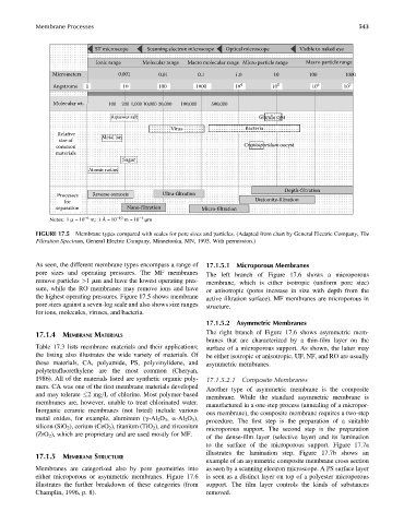
FIGURE 17.5 Membrane types compared with scales for pore sizes and particles. (Adapted from chart by General Electric Company, The
Filtration Spectrum, General Electric Company, Minnetonka, MN, 1993. With permission.)
As seen, the different membrane types encompass a range of 17.1.5.1 Microporous Membranes
pore sizes and operating pressures. The MF membranes The left branch of Figure 17.6 shows a microporous
remove particles >1 mm and have the lowest operating pres- membrane, which is either isotropic (uniform pore size)
sure, while the RO membranes may remove ions and have or anisotropic (pores increase in size with depth from the
the highest operating pressures. Figure 17.5 shows membrane active filtration surface). MF membranes are microporous in
pore sizes against a seven-log scale and also shows size ranges structure.
for ions, molecules, viruses, and bacteria.
17.1.5.2 Asymmetric Membranes
The right branch of Figure 17.6 shows asymmetric mem-
17.1.4 MEMBRANE MATERIALS
branes that are characterized by a thin-film layer on the
Table 17.3 lists membrane materials and their applications; surface of a microporous support. As shown, the latter may
the listing also illustrates the wide variety of materials. Of be either isotropic or anisotropic. UF, NF, and RO are usually
these materials, CA, polyamide, PS, polyvinylidene, and asymmetric membranes.
polytetrafluorethylene are the most common (Cheryan,
1986). All of the materials listed are synthetic organic poly- 17.1.5.2.1 Composite Membranes
mers. CA was one of the first membrane materials developed
Another type of asymmetric membrane is the composite
and may tolerate 2mg=L of chlorine. Most polymer-based
membrane. While the standard asymmetric membrane is
membranes are, however, unable to treat chlorinated water.
manufactured in a one-step process (annealing of a micropor-
Inorganic ceramic membranes (not listed) include various
ous membrane), the composite membrane requires a two-step
metal oxides, for example, aluminum (g-Al 2 O 3 , a-Al 2 O 3 ),
procedure. The first step is the preparation of a suitable
silicon (SiO 2 ), cerium (CeO 2 ), titanium (TiO 2 ), and zirconium
microporous support. The second step is the preparation
(ZrO 2 ), which are proprietary and are used mostly for MF.
of the dense-film layer (selective layer) and its lamination
to the surface of the microporous support. Figure 17.7a
illustrates the lamination step. Figure 17.7b shows an
17.1.5 MEMBRANE STRUCTURE
example of an asymmetric composite membrane cross section
Membranes are categorized also by pore geometries into as seen by a scanning electron microscope. A PS surface layer
either microporous or asymmetric membranes. Figure 17.6 is seen as a distinct layer on top of a polyester microporous
illustrates the further breakdown of these categories (from support. The film layer controls the kinds of substances
Champlin, 1996, p. 8). removed.