
Page 596 - Fundamentals of Water Treatment Unit Processes : Physical, Chemical, and Biological
P. 596
Membrane Processes 551
quantitative rating in terms of size of particles rejected, for The differences in transport models conceived by Sourir-
example, MWCO for RO membranes. ajan (1970) and Reid and Breton (1959) during the deve-
Membrane performance is judged primarily by two cri- lopmental stages of membrane filtration later divided
teria: (1) rejection fraction of intended solutes and (2) perme- researchers into two groups: (1) those that believe water and
ate flux density across the membrane and its rate of decline solute transport across asymmetric membranes is due to
due to fouling. These ‘‘dependent’’ variables are affected by a advection=diffusion transport, and (2) those that believe in a
number of ‘‘independent’’ variables, which include solution–diffusion transport model. Baker (2000, p. 8)
stated that the latter, that is, the solution–diffusion model,
1. Membrane pore size has been accepted since about 1980. The pores of an RO
2. Membrane composition membrane are on the order of magnitude of 3–5 Å and
3. Membrane configuration oscillate in size due to molecular vibration within the mem-
4. Feed-water quality brane polymer. As a rule of thumb, the transition from the
5. Changes in membrane properties due to induced solution–diffusion model to the pore-flow model is in the
stresses range of 5–10 Å (Baker, 2000, p. 19).
6. Concentration polarization The Poiseuille equation (Equation D.11), used in fluid
7. Operational parameters mechanics to describe laminar flow through pipes, is used
commonly to model advective transport through membrane
pores where the pressure differential on either side of the
17.3.3 MODELS DESCRIBING WATER AND SOLUTE
membrane drives the transport (Weber, 1972; Duranceau
FLUX THROUGH MEMBRANES
et al., 1992; Amjad, 1993; Laisure et al., 1993). That water
Several models have been proposed explaining the transfer of flux is proportional to the Dp across the membrane, and is
water and rejection of solutes by membranes. For micropor- inversely proportional to viscosity, is well established by
ous membranes, that is, MF and UF, most agree that water experimental evidence. What is not clear is that since an RO
moves across the membrane by advective transport and membrane has a homogeneous molecular structure that does
that the ‘‘rejected’’ suspended particles are physically not show discernable ‘‘pores,’’ the laminar flow model does
screened, that is, removed at the surface of the membrane not seem plausible (in the sense that the pipe flow model may
(Cheryan, 1986; AWWA, 1992). The permeate flow follows be valid, which assumes zero velocity at the pipe wall and a
the Poiseuille law, and is called the ‘‘pore-flow’’ model parabolic velocity distribution).
(Baker, 2000, p. 18).
For the asymmetric membranes, that is, NF and RO, the
explanation is not so clear. A number of models have been 17.3.4 BASIC NOTIONS FOR A CROSS-FLOW
proposed such as: diffusion and advection, solution–diffusion, MEMBRANE ELEMENT
pore flow, frictional models based on irreversible thermo-
A ‘‘cross-flow’’ membrane is by definition one in which the
dynamics, and empirical correlations (Pham et al., 1985).
‘‘feed flow’’ between two membrane sheets passes through the
Sourirajan (1970) in the late 1950s suggested a preferential
element and leaves it as ‘‘concentrate-flow.’’ The cross-flow
sorption=capillary model where water was preferentially
is diminished by the permeate flow along the axis of the
sorbed to the surface of the membrane while solutes experi-
membrane. Also, the cross-flow results in a shear along
ence preferential repulsion. This behavior was dependent on
the membrane surface, which may erode some deposits.
the both chemical nature of the membrane surface and the size
of the pores. This sorption of water and repulsion of solutes
resulted in the formation of a multimolecular layer of pure 17.3.4.1 Flow Balance
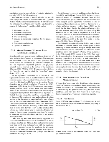
water at the membrane–solution interface (Sourirajan, 1970). Figure 17.12 (the same as Figure 17.1a) shows flows in and
This layer of pure water then flows through the pores of the out of a cross-flow type of membrane element, depicting a
membrane under pressure. According to this model, separ- flow balance, that is,
ation of solutes from the water occurs near the interface of the
solution and multimolecular layer of pure water. The chemical Q F ¼ Q P þ Q C (17:1)
nature of the membrane provides the conditions for sorption
of water and repulsion of solutes, but there is not a direct
sieving of solutes.
Later, work by Reid and Breton (1959) suggested that Q F Q P
water and solute transfer across CA membranes was due to Membrane
hydrogen bonding and diffusion. Ions and molecules in the
water that could form hydrogen bond with the membrane
would be transported across the membrane by alignment- Q C
type diffusion. Hole-type diffusion transport was explained
for ions and molecules unable to form hydrogen bond with the FIGURE 17.12 Flow balance definition sketch for a cross-flow
membrane (Sourirajan, 1970). type membrane element.