
Page 597 - Fundamentals of Water Treatment Unit Processes : Physical, Chemical, and Biological
P. 597
552 Fundamentals of Water Treatment Unit Processes: Physical, Chemical, and Biological
where where
3
Q F is the feed flow (m =s) R is the water recovery (dimensionless)
3
Q P is the permeate flow (m =s) R8 is the solute rejection (dimensionless)
3
Q C is the concentrate flow (m =s)
17.3.4.3 Water Flux Density
The flow balance is the basis for further definitions. The
Water flux density through a membrane is defined:
feed flow, Q F , is the influent flow to a given membrane element
after whatever pretreatment occurs. The permeate flow, Q P ,is
what passes through the membrane, and the concentrate flow, Q p
j (17:5)
Q C , leaves the membrane pressure vessel (but not through w A
the membrane).
2
where A ¼ surface area of the membrane (m ).
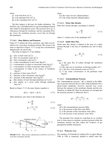
17.3.4.2 Mass Balance and Pressures
17.3.4.4 Solute Mass Flux
Figure 17.13 defines the flows, pressures, and solute concen-
Solute mass flux density is defined as the mass of a solute
trations for a cross-flow membrane element. The system is the
passing through a unit area of membrane per unit of time,
same as depicted in Figure 17.12 except that concentrations
that is,
and pressures are shown also.
The terms in Figure 17.13 are defined:
Q P C P
3
Q F ¼ flow of feed water (m =s) j ¼ A (17:6)
S
3
Q C ¼ flow of concentrate water (m =s)
3
Q P ¼ flow of permeate water (m =s) where
3
C F ¼ solute concentration in feed water (kg=m ) j S is the mass flux of solutes through the membrane
3
2
C C ¼ concentration of solute in concentrate water (kg=m ) (kg=s=m )
3
C P ¼ concentration of solute in permeate water (kg=m ) A is the total area of membrane in filtering module (m )
2
3
2
C m ¼ concentration of solute at the surface of membrane Q P is the flow of the permeate water (m =m =s)
3
(kg=m ) C P is the solute concentration in the permeate water
2
P F ¼ pressure of feed water (N=m ) (kg=m )
3
2
P C ¼ pressure of the concentrate water (kg=m )
2
P P ¼ pressure of the permeate water (kg=m )
3 2 17.3.4.5 Transmembrane Pressure
j w ¼ flux density of water through membrane (m =s=m )
j s ¼ flux density of a given solute through membrane The ‘‘transmembrane pressure,’’ DP,isdefined as the differ-
2
(kg=s=m ) ence in pressure between the two sides of the membrane. For a
spiral-wound membrane, however, pressure loss occurs
Based on Figure 17.13, the mass balance equation is between the entrance to the membrane element and the exit.
Therefore, to obtain DP, these two pressures are averaged and
(17:2) the permeate pressure is subtracted, that is,
Q F C F ¼ Q P C P þ Q C C C
Other definitions seen often in the literature are
P F þ P C
P P (17:7)
2
DP ¼
Q P
(17:3)
R
Q F
where
C F C P DP is the transmembrane pressure (kPa)
(17:4)
R
C F P F is the pressure of the feed water (kPa)
P C is the pressure of the concentrate water (kPa)
P P is the pressure of the permeate water (kPa)
C m The permeate flow should be controlled by an overflow
Membrane element
weir or some means to maintain a positive pressure within the
Q F C F P F Membrane Q P C P P P membrane element and thus reduce the incidence of gas
j s precipitation (bubble formation).
j w
Q C C C P C 17.3.5 POISEUILLE LAW
FIGURE 17.13 Mass balance and pressures definition sketch for a The equation of Poiseuille for laminar flow-in pipes (Rouse,
cross-flow membrane element. 1946, p. 158) is commonly adopted to model water flux