
Page 608 - Fundamentals of Water Treatment Unit Processes : Physical, Chemical, and Biological
P. 608
Membrane Processes 563
the addition of acid and anti-scalant followed by cartridge (i.e., 0.80–0.85 for high heads required), longer operating life,
filtration. The purpose of the acid was to lower the pH suffi- less space, and greater flexibility in adding additional stages.
ciently (from 7.2 to 6.8) to control CaCO 3 deposits on the The usual total dynamic head required was 1050 kPa (353 ft).
membranes. Polyacrylic acid anti-scalant was used. Cartridge The difference between the design TDH and the usual oper-
filtration was to remove silt and grit. Two pressure vessels of ating TDH was substantial and could be wasted or matched to
5 mm carridge filters were used; a 70 kPa (10 psi) pressure the conditions by a variable speed control. The latter was
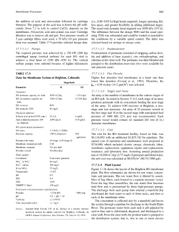
drop was assumed. Table 17.9 provides selected design data. selected based on savings in energy costs.
17.7.1.3.1 Pumps 17.7.1.3.2 Posttreatment
The required pressure was achieved by a 150 kW (200 hp) Posttreatment of permeate consisted of stripping carbon diox-
centrifugal pump (vertical turbine) for each RO skid to ide and addition of base (caustic), zinc orthophosphate, and
achieve a total head of 1350 kPa (450 ft). The vertical chlorine in the clear-well. The permeate was then blended and
turbine pumps were selected because of higher efficiencies pumped to the distribution reservoirs (two were available for
one pressure zone).
TABLE 17.9 17.7.1.3.3 Flux Density
Data for Membrane System at Brighton, Colorado Higher flux densities foul membranes at a faster rate than
lower flux densities (Cevaal et al., 1993). Therefore, the
Magnitude 2
j w ¼ 0.58 m=day (14.2 gpd=ft ) was selected.
Parameter SI US
17.7.1.3.4 Stages and Array
Parameter
3
RO permeate capacity per train 5050 m =day 1.333 mgd An array is the number of membranes in the various stages of
3
RO concentrate capacity per 1269 m =day 0.3326 mgd an RO rack. As noted in Section 17.4.2, each stage of an array
train produces permeate with its concentrate feeding the next stage
RO recovery 80% of the array. To achieve 0.80 recovery at Brighton, a two-
RO permeate TDS 45 mg=L stage unit was necessary. An array of 32 pressure vessels in
Chemical additions the first stage and 16 in the second stage with anticipated feed
Sulfuric acid in feed (93% conc.) 23 L=h 6 gal=h pressure of 1600 kPa (231 psi) was recommended. Each
Anti-scalant-hypersperse 100 1290 mL=h 0.34 gal=h pressure vessel would contain six standard 203 mm (8 in.)
(as shipped) diameter membranes.
RO system design parameters
17.7.1.3.5 Cost
RO trains 3 (1995); 5 (2000)
Permeate capacity 3505 L=min=train 926 The cost for the RO treatment facility, based on bids, was
gpm=train $6,118,892 with an additional $1,823,742 for pipelines. The
Pressure tube array 36 (stage 1):18 (stage 2) annual cost of operation and maintenance were projected as
Membrane element per tube 6 M $734,000, which included electric energy, chemicals, labor,
Membrane elements 324 per skid membrane replacement, equipment repairs and replacement,
Pressure vessels 54 tubes=skid insurance, and laboratory fees. Assuming annual production
3
Water quality rate of 10,500 m =day (2.77 mgd) of permeate and blend water,
3
Constituent Feed water (pretreat) the unit cost was calculated as $0.020=m ($0.74=1000 gal).
66 mg=L
NO 3 as NO 3
2 sulfate 296 mg=L 17.7.1.4 Plant Layout
SO 4
Si (as SiO 2 ) 25 mg=L Figure 17.24 shows the layout of the Brighton RO membrane
Temperature 13.48C
plant. The flow schematics are shown for raw water, concen-
pH 6.8
trate, and permeate. The raw water flow is filtered by assem-
SDI 0.4
blies of bag filters, each housed in a separate pressure vessel.
TDS 1070
From the bag filter assemblies, the raw water flow becomes
THMFP (7 days) 100 mg=L
feed flow and is pressurized by three high-pressure pumps.
Feed-water critical parameter specifications
The discharge from each pump then entered a manifold that
Pressure 2760 kPa 400 psig
distributed the feed water to each of three racks, and then to
pH 3.0 pH 10
each of the membrane tubes.
Turbidity 1.0 NTIJ
The concentrate is collected also by a manifold and leaves
Total suspended solids 1mg=L
the system through a pipeline for discharge to the South Platte
River. The permeate water from each rack is pH adjusted by
Source: Adapted from Cevaal, J.N. et al., Design of a reverse osmosis
treatment system for nitrate removal for Brighton, Colorado, in acid or base and is chlorinated, degassed, and discharged to a
AWWA Annual Conference, San Antonio, TX, June 6–10, 1993. clear well. From the clear well, the product water is pumped to
the distribution system, that is, first to one or more service