
Page 609 - Fundamentals of Water Treatment Unit Processes : Physical, Chemical, and Biological
P. 609
564 Fundamentals of Water Treatment Unit Processes: Physical, Chemical, and Biological
Fire Conference
Laboratory Office
pump room
Hall
Lobby
Passage Electrical Shop Women Men Concentrate Raw water Permeate
Operations
Clear-well
F
P
F
Membranes P
F
P P P P De-gasing
P
Future Future Skid #3 Skid #2 Skid #1
skid #5 skid #4 Cleaning tanks
Chlorination cylinders
Acid Caustic
Passage Anti-scalant Passage Chlorination Passage Passage
scrubber
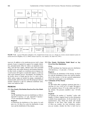
FIGURE 17.24 Layout of RO plant at Brighton, CO. (Adapted from Cevaal, J.N. et al., Design of a reverse osmosis treatment system for
nitrate removal for Brighton, CO, in: AWWA Annual Conference, San Antonio, TX, June 6–10, 1993.)
reservoirs. In addition to the membrane process itself, a large 17.2 Flux Density Distribution Model Based on Any
amount of space is required for support, for example, labora- Given Pore-Size Distribution
tory, personnel needs, lobby for visitors, an operations room, Given
shop, acid and base supply, chlorine room with associated An MF membrane has Gaussian pore-size distribution
scrubber room, anti-scalant chemical, and cleaning chemicals.
with d(pore)avg ¼ 1.2 mm and s ¼ 0.22 mm.
In other words, as simple as a membrane process appears, the
Required
overall system still requires considerable support, as with any
(a) Determine the distribution of flux density. (b) Show
other water treatment process. Nevertheless, the building for
by a plot the distribution of pore sizes and the distribu-
the facility shown is simple and the floor is a slab in parts,
tion of flux density. (c) Set up a general mathematical
albeit various sumps are needed for pumps, containment of
model that would apply to any distribution.
chemical spills, and for the clear well. The design provided for
17.3 Calculation of Flux Density
modular expansion to add two additional membrane racks,
which were added in 2003. Given
An MF hollow-fiber membrane treatment plant has a
3
PROBLEMS total flux, Q J w ¼ 0.657 m =s (15 mgd). The plant is
to be operated at about 28C in the winter and 208Cin
17.1 Flux Density Distribution Based on Pore-Size Distri- the summer. The pressure available is Dp ¼ 138 kPa
bution (20 psi).
Given Required
An MF membrane has pore-size distribution as follows: (a) Estimate the number of ‘‘modules’’ (tubes with
bundles of fibers) required based on the information
d(pore)0.33 fraction ¼ 1.5 mm, d(pore)0.33 fraction ¼
1.0 mm, and d(pore)0.33 fraction¼ 0.5 mm. available from manufacturers. (b) If provided by the
Required manufacturer’s data, obtain the inside and outside
(a) Determine the distribution of flux density for each diameters of the fibers, their length, the number
pore size. (b) Show by a plot the distribution of pore of fibers per module, the total membrane surface
sizes and the distribution of flux density. area per module, whether the fiber is shell feed or