
Page 628 - Fundamentals of Water Treatment Unit Processes : Physical, Chemical, and Biological
P. 628
Gas Transfer 583
Motor Turbine
Circulation
pattern
(a) (b)
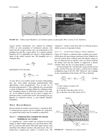
FIGURE 18.6 Turbine aerator illustrations. (a) Circulation pattern, (b) photograph. (Photo courtesy of S.K. Hendricks.)
oxygen transfer mechanisms were outlined by Kalinske ‘‘plug-flow’’ model is used most often for diffused aeration,
(1963), an early proponent of mechanical aeration, who which occurs in a long narrow basin.
stated that the oxygen transfer rate was proportional to the
pumping rate and the oxygen deficit. As a general relation, 18.2.3.1.1 General Mass Balance: Kinetic Relations
Equation 18.21 is applicable, but with K L a, being defined in Figure 18.7 depicts a continuous-flow complete-mix reactor,
terms of the surface renewal rate. The pumping rate is a which shows the mass balance and kinetic terms. Bubbles rise
surrogate; thus, from the bottom from a diffuser grid and transfer oxygen as
they are dispersed by an impeller; some are always breaking
the surface such that the number in suspension is always
KQ W
(18:47)
K L a ¼ constant. Thus, the rate of oxygen uptake is constant.
V
As seen in Figure 18.7, the mass flux of gas into the reactor
is QC in and the mass flux out is QC out , and the rate of uptake
and Equation 18.21 becomes
or depletion of gas is [qC=qt] r . The ‘‘observed’’ rate of change
of gas concentration in the reactor, [qC=qt] o is therefore
dC KQ W
(C s C) (18:48)
¼
dt V qC qC
V ¼ QC in QC out þ V (18:49a)
qt o qt r
As seen, the K L a for a turbine aerator increases with pumping
rate, Q w , most likely increasing proportionately then
where
approaching a limit asymptotically. Also, as seen, K L a is 3
V is the volume of reactor (m )
inversely proportional to V. The coefficient, K L a, incorporates
t is the time (s)
a variety of influences, including diffusivity, turbulence inten- 3
Q in is the flow into the reactor (m =s)
sity, circulation patterns as affected by geometry of the tank, 3
Q out is the flow out of the reactor (m =s)
etc. As for diffused aeration, the K L a term is unique for a
particular aerator–aeration tank system. The pumping rate, Q w
depends on rotational velocity, v, and impeller diameter, Impeller
d(impeller).
18.2.3 REACTOR MODELING
Reactor models for aeration may be batch, or continuous flow.
A continuous-flow reactor may be complete mix, plug-flow,
Q C in Q out C out
in
or a packed bed (which may be modeled as plug-flow).
18.2.3.1 Continuous-Flow Complete-Mix Reactor
Modeling for Gas Transfer
A ‘‘complete-mix’’ reactor model was common for activated
sludge in which turbine aeration was used from about 1962, dC = K a(C –C)
L
s
but was used less after about 1980 when many reactors were dt r
retrofitted with diffused aeration with grid layout. The con-
tinuous-flow complete-mix model is reviewed here. The FIGURE 18.7 Continuous-flow aeration reactor.