
Page 629 - Fundamentals of Water Treatment Unit Processes : Physical, Chemical, and Biological
P. 629
584 Fundamentals of Water Treatment Unit Processes: Physical, Chemical, and Biological
C in is the dissolved gas concentration of flow into the Figure 18.8b is a photograph that illustrates the extremely
3
reactor (kg gas=m ) high level of turbulence generated by the flow of diffused air
C out is the dissolved gas concentration of flow out of the through the perforated bottom. The value of K L a for such a
3
reactor (kg gas=m ) unit is undoubtedly much higher than any traditional air
[qC=qt] o is the observed rate of change of dissolved gas stripping technology, due mostly to the high rate of air–
3
concentration within the reactor (kg gas=m =s) water interface area created, and to a lesser extent due to
[qC=qt] r is the rate of dissolution of gas within the reactor the small film thickness created by the high turbulence inten-
3
(kg gas=m =s) sity. An issue with applying the above analysis to the
ShallowTraye technology is that being a channel, it is not a
The sign for the kinetic term, [qC=qt] r , in Equation 18.49a, is compete-mix reactor. It is probably not a too inaccurate
taken as positive since the proper sign will emerge when the model, however, for understanding how the system works.
details of the kinetic situation is known. For the case of gas Usually, a system such as the ShallowTraye is selected based
transfer, the kinetic term is given by Equation 18.20, that is, on experience, perhaps coupled with a pilot plant study
[qC=qt] r ¼ K L a(C s C). If C < C s , then gas is transferred to (see also http:==www.neepsystems.com).
the aqueous solution from the gas phase; thus the kinetic term
is positive. If C > C s , then gas must be transferred from the 18.2.3.2 Batch Reactor Aeration Modeling
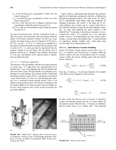
aqueous solution to the gas phase; thus the kinetic term is Figure 18.9 depicts a batch aeration reactor, that is, Q in ¼ 0.
negative and the gas is ‘‘stripped’’ from solution. Recall that Q out ¼ 0; therefore, the observed rate of change within the
C s is the gas concentration in the aqueous phase in equilib- reactor is equal to the rate of dissolution of gas, for example,
rium gas phase pressure. oxygen, within the reactor. Starting again with the general
reactor statement,
18.2.3.1.2 Proprietary Equipment
The pressure in the gas bubbles (and thus the partial pressure qC qC
V ¼ Q in C in Q out C out þ V (18:49b)
of a given gas, ‘‘A’’) approaches zero gauge-pressure for a qt o qt r
ShallowTraye type of air stripping unit, since the depth of the
unit is less than a meter. The gas transfer occurs largely across Since Q in ¼ 0and Q out ¼ 0, and since Equation 18.21 applies
the large air–water interface area created and the evident high to the [qC=qt] r term, Equation 18.49 becomes
turbulence intensity. Figure 18.8a is a perspective drawing of
a unit, which consists of a flow of water through open chan-
qC
nels over a perforated bottom through which a flow of air V ¼ 0 0 þ V K L a(C s C) (18:50)
qt
bubbles emerge under pressure. The amount of turbulence and o
the shallow depth of the channels ensure that the bubbles do
and
not have long residence time (which would accumulate the
gas being stripped).
qC
¼ K L a(C s C) (18:51)
qt
o
In other words, the observed rate of increase in dissolved
oxygen concentration equals the rate of oxygen uptake by
the aeration system. That [qC=qt] o 6¼ 0 means, by definition,
that the reactor state is not ‘‘steady state.’’ The foregoing
Rising bubbles
Q in =0 Q out =0
(a) (b)
FIGURE 18.8 ShallowTraye stripping unit for dissolved gases. dC =K a(C s –C)
(a) Perspective drawing of unit, (b) photograph illustrating turbu- dt L
lence. (Courtesy of BISCO Environmental NEEP Systems, Inc.,
Taunton, MA, 2010.) FIGURE 18.9 Batch aeration reactor.