
Page 634 - Fundamentals of Water Treatment Unit Processes : Physical, Chemical, and Biological
P. 634
Gas Transfer 589
20 will not be the rate limiting part of the process for
Diffuser = 203 mm (8 in.) stripping a low solubility gas such as oxygen. If
V(tank) =30 L
a highly soluble gas, for example, ammonia, is
15 stripped, the control would shift to the gas phase.
K L a (h –1 ) 10 18.3 DESIGN
As seen in ‘‘theory,’’ the mass-transfer coefficient, K L a,is
a single design parameter that integrates several fundamental
variables. The value of K L a, along with the gradients within
5 the gas film and the aqueous film, determine the gas transfer rate.
Air
O 2 As a rule, K L a is proportional to the rate of creation of
interface area, which for a given design, depends upon oper-
N 2
0 ating conditions, for example, higher rotational velocity for an
0 100 200 300 400 500 turbine aerator, high airflow for an air stripping tower, etc.
Q΄(L/h) The intent is not necessarily to maximize K L a, but to find an
overall design that is economical.
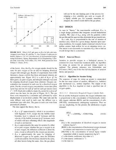
FIGURE 18.13 Effect of Q and gases on K L a for lab-scale tests.
0
(Adapted from Clunie, W. and Wu, Y., Gas Transfer Coefficients for
Bubble Diffusers, CE 541 Unit Processes of Environmental Engin-
18.3.1 AERATOR DESIGN
eering Laboratory, Spring, Department of Civil Engineering, Color-
ado State University, Fort Collins, CO, 1995. With permission from Aeration to provide oxygen to a biological process is
William F. Clunie, 2010.) common for every wastewater treatment plant. An algorithm
for sizing an aerator for an activated sludge reactor is
outlined. The primary reference was Eckenfelder and
of the basin). Also, the K L a for oxygen uptake should be the
O’Connor (1961), one of the first full elucidations of aeration
same for pure oxygen as for air and for stripping dissolved
theory and practice.
oxygen with nitrogen gas. Results of experiments from CSU
laboratory classes confirm that these anticipated relations are
18.3.1.1 Algorithm for Aerator Sizing
approximately true. Figure 18.13 is a plot of K L av. Q for
0
three gases, air, pure oxygen, and nitrogen (nitrogen was used The sequence of steps for sizing an aerator is enumerated
for stripping dissolved oxygen from solution). Oxygen con- for the two main classes of aerators, diffused (i.e., bubbles)
centration was measured in each case by a dissolved oxygen and mechanical (i.e., turbine impeller). The output of the
probe. For the several oxygen concentration versus time plots algorithm is the K L a required to meet a specified rate of
(semi-log) and one for each Q and for each gas species used, oxygen uptake.
0
2
r 0.99. Each plot yielded a single K L a point for a given Q 0
which was the basis for the plot of Figure 18.13. The gas 18.3.1.1.1 Determine Required Oxygen Uptake Rate
flows were measured by a rotometer and calibrated by water For an aerobic biological reaction, the oxygen utilization rate
displacement of an inverted cylinder. The same tank and the is proportional to the concentration of biochemically oxidiz-
same diffuser were used in each case; the diffuser was a able organic substrate (BOD), and the concentration of cells
membrane type with slots. The gases in each case were from (MLVSS), simultaneously undergoing respiration. Thus we
pressurized cylinders. can say (neglecting, for the present, the nitrification oxygen
The data support the theory, that is, demand)
. K L a / Q (approximately), which is in accordance
0
d[O 2 ]
with Equation 18.45, except that the bubble–water ¼ a [BOD] R þ b [MLVSS] R (18:62)
0
0
dt
boundary layer is reduced as Q increases and the
0
velocity of the bubble increases as Q increases, each
0
of which will have offsetting effects (the magnitude where
of each is not known). [O 2 ] is the concentration of dissolved oxygen in reactor
3
. K L a is approximately the same for aeration by either solution (kg=m )
air or pure oxygen; whether the gas is oxygen in air [BOD] is the concentration of biochemical oxygen demand
3
or pure oxygen, the diffusion coefficient is about the in solution and suspension in reactor (kg=m )
same, except as affected by the oxygen gas pressure. [MLVSS] is the concentration of mixed liquor volatile
3
. K L a is approximately the same for stripping of suspended solids in reactor suspension (kg=m )
1
dissolved oxygen as for uptake, since the diffusion a is the kinetic coefficient, first order (s )
0
1
coefficient and the film thickness should be the same, b is the kinetic coefficient (s )
0
all other factors being the same. Also, the gas phase t is the time (s)